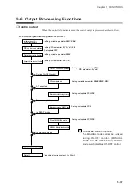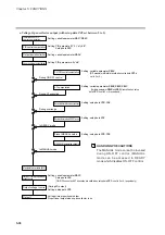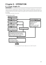
Chapter 6. OPERATION
6-2 Basic Display Selection
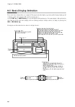
The console basic display status is comprised of the program number display, segment number display, display panel
1, display panel 2, basic display LEDs and the message panel.
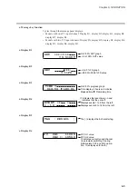
Use the
DISP key
or
MESSAGE key
to cycle through the different displays. The mode display LEDs perform the
same functions both in the basic display status and during parameter settings and do not change by pressing the
DISP
or
MESSAGE key
.
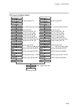
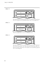
The displays and their functions are shown in the figure below.
CYC
OUT
DEV
PV
SP
TM
SYN
PROG
SEG
PROFILE
Program and segment number display
Program
number
Segment
number
PV
SP
Pattern trend
Displays the program and segment number of
the selected program in the READY program run mode.
Displays the program and segment number of the
program and segment number of the currently running
program in modes other than READY mode.
Both displays are off in the fixed command control mode.
Profile display
Indicates when a program has been set in
program run mode. The display is off when no
setting has been made.
When a setting has been made, but there is
no next segment the three LEDs on the right
are off.
This display is off in the fixed command control
mode.
Display panel 1
Display
panel 2
Basic display LEDs
The LEDs go on when respective
function is operating.
Detailed descriptions follow.
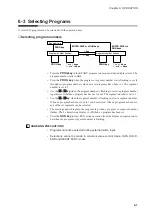
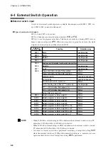
PROFILE
(4)Rising temperature lamp
(5)SOAK
(6)Falling temperature lamp
(1)Falling temperature lamp
(2)SOAK
(3)Rising temperature lamp
Current
segment
Next
segment
6-2
Содержание DCP550
Страница 1: ...EN1I 6186 Issue 13 04 08 DCP551 Mark ΙΙ Digital Control Programmer User s Manual www honeyvell energy ...
Страница 115: ...Chapter 7 PARAMETER SETUP Settings by event type For information on event operations see Events pages 5 5 to 5 15 7 13 ...
Страница 117: ...Chapter 7 PARAMETER SETUP 0 1 02 3 02 3 0 1 1 4 5 1 4 6 1 4 5 2 2 2 7 15 ...
Страница 119: ...Chapter 7 PARAMETER SETUP 0 11 2 2 3 3 7 17 ...
Страница 122: ...Chapter 7 PARAMETER SETUP d A5 tP A5 CP A5 rE A5 P A6 I A6 d A6 rE A6 CP A6 tP A6 P A7 I A7 d A7 rE A7 CP A7 tP A7 7 20 ...
Страница 209: ...Chapter 12 CALIBRATION Figure 12 11 Current Outputs 12 18 ...
Страница 229: ......
Страница 230: ...No CP UM 5024E ...

