


Chapter 6
6-8
6.4
Parts Replacement Procedure
6.4.1 Laser Scanner Unit
6.4.1.1 Before Starting the Work
0011-7559
1) Remove the manual feed pull-off roller unit.
2) Remove the developing assembly locking
plate.
3) Remove the developing assembly.
4) Remove the sub hopper unit.
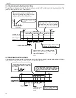
6.4.1.2 Removing the Laser Scanner Unit
0010-8803
1) Disconnect all connectors [1], and detach the 2
anti-vibration plates [2].
- 2 screws [3]
F-6-8
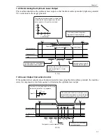
2) Remove the laser scanner unit [1].
- 2 bosses [2]
F-6-9
6.4.1.3 When Replacing the Laser
Scanner Unit
0010-8804
There is no special work in conjunction with the
replacement of the laser scanner unit.
[1]
[2]
[2]
[3]
[1]
[2]
Содержание IMAGERUNNER 7095 PRINTER
Страница 20: ...Chapter 1 Introduction...
Страница 46: ...Chapter 2 Installation...
Страница 88: ...Chapter 3 Basic Operation...
Страница 94: ...Chapter 4 Main Controller...
Страница 116: ...Chapter 5 Original Exposure System...
Страница 165: ...Laser Exposure Chapter 6...
Страница 175: ...Chapter 7 Image Formation...
Страница 180: ...Chapter 7 7 3 7 3 Basic Sequence 7 3 1 Basic Sequence 0010 8038 F 7 3 ON ON WMUPR WMUP STBY OFF 100msec...
Страница 231: ...Chapter 8 Pickup Feeding System...
Страница 287: ...Chapter 9 Fixing System...
Страница 312: ...Chapter 10 External and Controls...
Страница 346: ...Chapter 11 MEAP...
Страница 350: ...Chapter 12 RDS...
Страница 360: ...Chapter 13 Maintenance Inspection...
Страница 375: ...Chapter 14 Standards Adjustments...
Страница 407: ...Chapter 15 Correcting Faulty Images...
Страница 433: ...Chapter 16 Self Diagnosis...
Страница 460: ...Chapter 17 Service Mode...
Страница 559: ...Chapter 18 Upgrading...
Страница 583: ...Chapter 19 Service Tools...
Страница 584: ...Contents Contents 19 1 Service Tools 19 1 19 1 1 Special Tools Table 19 1 19 1 2 Solvents Oils 19 2...
Страница 588: ...APPENDIX...
Страница 615: ......


