


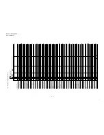
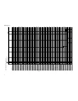


7
General Circuit Diagram
General Circuit Diagram (1/20)
F-2-1
A
4
3
2
C
B
D
E
F
A
C
B
D
E
F
7
6
5
1
4
3
2
7
8
8
6
5
1
SW1
SW3
Environment switch
FOR Finisher
TO Peper Deck heater
AC POWER UNIT1
H2
H1
H3
H4
AC POWER UNIT2
AC driver PCB
AC driver sub PCB
All night power supply PCB
DC power supply PCB
Main switch
Fixing unit
Fixing
sub
heater
Fixing
main
heater
Drum heater
control PCB
Drum heater
Cassette heater
(1/20)
Содержание IMAGERUNNER 7095 PRINTER
Страница 20: ...Chapter 1 Introduction...
Страница 46: ...Chapter 2 Installation...
Страница 88: ...Chapter 3 Basic Operation...
Страница 94: ...Chapter 4 Main Controller...
Страница 116: ...Chapter 5 Original Exposure System...
Страница 165: ...Laser Exposure Chapter 6...
Страница 175: ...Chapter 7 Image Formation...
Страница 180: ...Chapter 7 7 3 7 3 Basic Sequence 7 3 1 Basic Sequence 0010 8038 F 7 3 ON ON WMUPR WMUP STBY OFF 100msec...
Страница 231: ...Chapter 8 Pickup Feeding System...
Страница 287: ...Chapter 9 Fixing System...
Страница 312: ...Chapter 10 External and Controls...
Страница 346: ...Chapter 11 MEAP...
Страница 350: ...Chapter 12 RDS...
Страница 360: ...Chapter 13 Maintenance Inspection...
Страница 375: ...Chapter 14 Standards Adjustments...
Страница 407: ...Chapter 15 Correcting Faulty Images...
Страница 433: ...Chapter 16 Self Diagnosis...
Страница 460: ...Chapter 17 Service Mode...
Страница 559: ...Chapter 18 Upgrading...
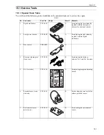
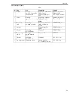
Страница 583: ...Chapter 19 Service Tools...
Страница 584: ...Contents Contents 19 1 Service Tools 19 1 19 1 1 Special Tools Table 19 1 19 1 2 Solvents Oils 19 2...
Страница 588: ...APPENDIX...
Страница 615: ......