


Chapter 7
7-6
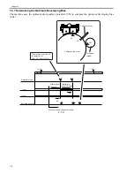
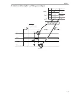
7.4.3 Determining the Optimum Grid Bias
0010-8041
The grid bias is determined so that the drum surface potential will be identical to the target potential. (The
primary charging bias is set to a fixed value.)
F-7-7
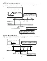
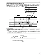
7.4.4 Grid Bias Corrective Control
0010-8042
If the optimum grid bias cannot be determined at the end of drum surface potential measurement, the ma-
chine starts its compensatory control sequence to determine the bias.
F-7-8
WMUPR
WMUP
STBY
193
198
Potential sensor
Primary charging bias
Grid bias
650 V
550 V or 750 V
Measurement(VD2) Measurement(VD1orVD3) Measurement (target VD)
Vg
550V 650V 750V
VD1
VD2
VD3
Grid bias
Measurements are taken multiple times to
determine the relationship between the drum
surface potential (VD) and the grid bias.
A grid bias (Vg) needed to attain
the target VD is determined.
Potential control sequence started
Charging characteristics
curve
If the target VD is attained using this
measurement, the control is ended;
otherwise, compensatory control is
After measuring VD2, VD1 will be measured
if VD2 is greater than the target VD; if smaller,
VD3 will be measured.
WMUPR
WMUP
STBY
193
198
Potential sensor
Primary charging bias(DC)
Grid bas
650 V
550 V
or
750 V
Vg
Vg1 Vg2 Vg3
Vg8
VD1
VD-NG
VD2
VD3
Continues to take measurements while varying
the value of the grid bias so that it will be closer
to the target VD.
Potential control
sequence started
Compensatory control
sequence started
VD-NG VD1 VD2
VD3
VD8
TargetVD
A grid bias (Vg) needed to attain the
target VD is determined.
When the measurement is identical to the target VD,
ends the control. The machine executes measurement a
maximum of 8 times, possibly using an approximate
target VD.
Содержание IMAGERUNNER 7095 PRINTER
Страница 20: ...Chapter 1 Introduction...
Страница 46: ...Chapter 2 Installation...
Страница 88: ...Chapter 3 Basic Operation...
Страница 94: ...Chapter 4 Main Controller...
Страница 116: ...Chapter 5 Original Exposure System...
Страница 165: ...Laser Exposure Chapter 6...
Страница 175: ...Chapter 7 Image Formation...
Страница 180: ...Chapter 7 7 3 7 3 Basic Sequence 7 3 1 Basic Sequence 0010 8038 F 7 3 ON ON WMUPR WMUP STBY OFF 100msec...
Страница 231: ...Chapter 8 Pickup Feeding System...
Страница 287: ...Chapter 9 Fixing System...
Страница 312: ...Chapter 10 External and Controls...
Страница 346: ...Chapter 11 MEAP...
Страница 350: ...Chapter 12 RDS...
Страница 360: ...Chapter 13 Maintenance Inspection...
Страница 375: ...Chapter 14 Standards Adjustments...
Страница 407: ...Chapter 15 Correcting Faulty Images...
Страница 433: ...Chapter 16 Self Diagnosis...
Страница 460: ...Chapter 17 Service Mode...
Страница 559: ...Chapter 18 Upgrading...
Страница 583: ...Chapter 19 Service Tools...
Страница 584: ...Contents Contents 19 1 Service Tools 19 1 19 1 1 Special Tools Table 19 1 19 1 2 Solvents Oils 19 2...
Страница 588: ...APPENDIX...
Страница 615: ......


