background image

Chapter 8  

8-10

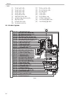
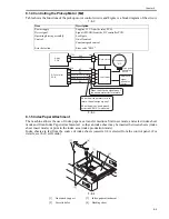
8.4.3 Detecting the Level of Paper
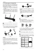
0010-8202

The machine indicates the level of paper inside the deck and the cassette in four readings (including No
Paper) on the control panel.

T-8-7

In the case of the deck right/left, two sensors are used to detect the position of the deck, and combinations
of the states of the sensors (on/off) are used to find out the level of paper.
For the absence of paper, an exclusive sensor is used. 

F-8-15

T-8-8

In the case of cassette 3/4, the resistance of the variable resistor operating in conjunction with the move-
ment of the lifter drive shaft is used to find out the level of paper.

Level of paper

Indication on control panel

100% to about 50% of capacity

about 50% to about 10% of capacity

about 10% of capacity or less

No paper

Deck right

Deck left

Paper level

[1] Sensor 
(PS51)

[2] Sensor 
(PS52)

Sensor 
(PS22)

[1] Sensor 
(PS54)

[2] Sensor 
(PS55)

Sensor 
(PS32)

100% to about 50%

ON

ON

OFF

ON

ON

OFF

About 50% to about 10

OFF

ON

OFF

OFF

ON

OFF

About 10% or less

OFF

OFF

OFF

OFF

OFF

OFF

None

OFF

OFF

ON

OFF

OFF

ON

Paper level
(100% to 
about 50%)

Paper level 

     (about 50% to 

about 10%)

Paper level

                   (about 10% 

            or less)

[2]

[1]

[1]

[1]

[2]

[2]

DC controller PCB

Main controller PCB

Содержание IMAGERUNNER 7095 PRINTER

Страница 1: ...SERVICE MANUAL imageRUNNER 7105 7095 7086 COPYRIGHT 2005 CANON INC CANON imageRUNNER 7105 7095 7086 REV 0 PRINTED IN U S A DU7 1166 000 NOVEMBER 2005 REV 0...

Страница 2: ...need arises In the event of major changes in the contents of this manual over a long or short period Canon will issue a new edition of this manual The following paragraph does not apply to any countri...

Страница 3: ...uiring care to avoid combustion fire Indicates an item prohibiting disassembly to avoid electric shocks or problems Indicates an item requiring disconnection of the power plug from the electric outlet...

Страница 4: ...ed to indicate Low The voltage value how ever differs from circuit to circuit In addition the asterisk as in DRMD indicates that the DRMD signal goes on when 0 In practically all cases the internal me...

Страница 5: ...9 1 2 3 2 Timer Settings 1 12 1 2 3 3 Adjustment Cleaning 1 13 1 2 3 4 Report Settings 1 14 1 2 3 5 System Settings 1 14 1 2 3 6 Copy Settings 1 16 1 2 3 7 Communications Settings 1 17 1 2 3 8 Mail B...

Страница 6: ...g the Lead Edge Registration 2 29 2 2 19 Setting the Cassette 2 29 2 2 20 Correcting the Skew 2 29 2 2 21 Switching Over the Paper Size for the Front Deck right left 2 30 2 2 22 Checking the Operation...

Страница 7: ...6 4 6 4 Boot ROM 4 16 4 6 5 HDD 4 17 4 6 6 Video PCB 4 18 4 6 7 Reader I F PCB 4 19 4 6 8 Controller Fan 4 20 Chapter 5 Original Exposure System 5 1 Construction 5 1 5 1 1 Specifications Controls and...

Страница 8: ...de iR7086 5 18 5 3 5 3 White Plate Dust Detection Control 5 19 5 3 6 Image Processing 5 20 5 3 6 1 Overview iR7105 7095 5 20 5 3 6 2 Overview iR7086 5 21 5 3 6 3 CCD Drive iR7105 7095 5 22 5 3 6 4 CCD...

Страница 9: ...ics Sequence of Operations 7 5 7 4 3 Determining the Optimum Grid Bias 7 6 7 4 4 Grid Bias Corrective Control 7 6 7 4 5 Determining the Optimum Laser Output 7 7 7 4 6 Laser Output Corrective Control 7...

Страница 10: ...er Deposit 7 34 7 9 1 3 Correcting the Output upon Detection of Leakage 7 34 7 9 1 4 Others 7 34 7 10 Parts Replacement Procedure 7 35 7 10 1 Process Unit 7 35 7 10 2 Pre Exposure Lamp 7 36 7 10 3 Pri...

Страница 11: ...6 8 6 1 Outline 8 16 8 6 2 Lifter Limiter deck right left 8 17 8 6 3 Detecting the Presence Absence of Paper 8 18 8 6 4 Detecting the Level of Paper 8 18 8 6 5 Cassette Deck Right Left 8 19 8 7 Regist...

Страница 12: ...ssion 8 51 8 11 25 Double Feeding Detection Sensor Reception 8 53 Chapter 9 Fixing System 9 1 Construction 9 1 9 1 1 Outline 9 1 9 1 2 Major Components 9 1 9 1 3 Overview of the Fixing Drive System 9...

Страница 13: ...7095 10 5 10 3 3 Sequence of Fan Operation 10 6 10 4 Power Supply System 10 7 10 4 1 Power Supply 10 7 10 4 1 1 Overview of the Power Supply System 10 7 10 4 2 Backup Battery 10 7 10 4 2 1 Back Up Ba...

Страница 14: ...ling Fan 10 27 10 5 35 De Curling Fan 10 27 10 5 36 Drum Fan 10 28 10 5 37 Pre Transfer Charging Assembly Fan 10 28 10 5 38 Power Supply Cooling Fan 1 10 28 10 5 39 Power Supply Cooling Fan 2 10 29 10...

Страница 15: ...14 2 14 1 4 Making Checks on the Printer Side Checking the Solid Black Density 14 3 14 1 5 Making Checks on the Printer Side Checking for fogging 14 4 14 1 6 Making Checks on the Printer Side Checking...

Страница 16: ...Cassette Separation Roller 14 26 14 8 8 Adjusting the Pressure of the Pickup Feeding Roller of the Manual 14 26 14 8 9 Location of the solenoids 14 27 14 8 10 Position of the Fixing Web Solenoid SL2 1...

Страница 17: ...C controller PCB 15 24 Chapter 16 Self Diagnosis 16 1 Error Code Table 16 1 16 1 1 Error Code Table 16 1 16 2 Error Code Details 16 3 16 2 1 Error Code Details 16 3 16 2 2 Detail in E602 16 15 16 3 Ja...

Страница 18: ...tems 17 59 17 6 OPTION Machine Settings Mode 17 60 17 6 1 COPIER 17 60 17 6 1 1 COPIER Items 17 60 17 6 1 2 Soft Counter Specifications 17 77 17 6 2 FEEDER 17 86 17 6 2 1 FEEDER Items 17 86 17 6 3 SOR...

Страница 19: ...18 13 18 4 3 Uploading and Downloading Backup Data 18 15 18 4 3 1 Outline 18 15 18 4 3 2 Uploading Procedure 18 16 18 4 3 3 Downloading Procedure 18 17 18 4 4 Version Upgrade using USB 18 18 18 4 4 1...

Страница 20: ...Chapter 1 Introduction...

Страница 21: ...ntrol Panel 1 9 1 2 3 User Mode Items 1 9 1 2 3 1 Common Settings 1 9 1 2 3 2 Timer Settings 1 12 1 2 3 3 Adjustment Cleaning 1 13 1 2 3 4 Report Settings 1 14 1 2 3 5 System Settings 1 14 1 2 3 6 Cop...

Страница 22: ...her V1 3 Saddle Finisher V2 4 Document Insertion Unit C1 5 Paper Folding Unit D1 6 Punch Unit U1 V1 W1 X1 7 High Capacity Stacker A1 8 Booklet Trimmer B1 9 Professional Puncher A1 10 Paper Deck W1 11...

Страница 23: ...2 Either a professional puncher or a punch unit may be used A trimmer must be used in combination with a saddle finisher 2 Main Unit High Capacity Stacker F 1 3 A Professional Puncher outside Japan D...

Страница 24: ...r a professional puncher or a punch unit may be used A trimmer must be used in combination with a saddle finisher A High Capacity Stacker E Finisher B Professional Puncher outside Japan F Insertion Un...

Страница 25: ...9 Remote Operators Software Kit A1 license certificate 10 Voice Guidance Kit A2 11 Barcode Printing Kit B1 license certificate 12 Security Mark A1 license certificate UFR II PCL PS printing PDF Tiff...

Страница 26: ...very tray 6 Upper right cover 21 Reader rear cover 7 Rear right upper cover 22 Reader left cover 8 Manual feeder tray 23 Upper left cover 9 Rear right lower cover 24 Lower left cover 10 Upper right do...

Страница 27: ...charging assembly 36 Left deck separation roller 8 Photosensitive drum 23 Right deck pickup roller 37 Left deck feeding roller 9 Primary charging assembly 24 Right deck feeding roller 38 Left deck pic...

Страница 28: ...e goes on when the main power switch is turned on To end power save mode low power mode or sleep mode turn on the control panel power switch F 1 8 1 Control panel power switch 2 Main power lamp 3 Main...

Страница 29: ...n sequence while keeping the following in mind 1 be sure that the Execute Memory lamp on the control panel is off 2 do not turn off the main power switch while downloading is under way Otherwise the m...

Страница 30: ...ol panel power switch 15 Touch panel display 8 Numeric keys Item Settings Initial Function Select Initial Function Copy 1 Send Mail Box MEAP Set System Monitor as the Initial Function On Off 1 Set the...

Страница 31: ...the Optionl Finisher V1 or Saddle Finisher V2 Is Attached Tray A Copy 1 Mail Box 1 Printer 1 Receive 1 Other 1 Tray B Copy 1 Mail Box 1 Printer 1 Receive 1 Other 1 If the Optional Finisher V1 or Sadd...

Страница 32: ...t Collate 1 Group Offset Group If the Optional High Capacity Stacker A1 and Finisher V1 or Saddle Finisher V2 Are Attached Do Not Collate Collate Offset Collate 1 Group Offset Group Staple Corner Top...

Страница 33: ...2 Finisher Tray A B ON OFF 1 Finisher Saddle Stitcher Unit ON OFF 1 Finisher Inserter ON OFF 1 Folding Unit ON OFF 1 Puncher Unit ON OFF 1 Stacker ON OFF 1 Shutdown Mode Press Start Initialize Common...

Страница 34: ...02 0 05 mm increments 0 010 0 25 mm 1 Exposure Recalibration Copy Inbox Send Light Dark 1 to 9 levels 5 1 Character Background Contrast Adjustment Relative Contrast Value 7 to 7 0 1 Sample Print Sampl...

Страница 35: ...ager 32 characters maximum E mail Address 64 characters maximum Contact Information 32 characters maximum Comment 32 characters maximum Dept ID Management Deppt ID Management On Off 1 Register Dept ID...

Страница 36: ...ttings Register Destinations Select All Auto Search Register Register Details Erase Print List Auto Delivery Settings Everyday Select Days Off 1 Add Functions Settings Value On Network Settings Includ...

Страница 37: ...1 to 9 999 1 1 Serial Number Print Dept ID Print Item Settings Screen Display Setting Regular Copy Only 1 Regular and Express Copy Express Copy Only Regular Copy Screen Priority On 1 Off Paper Select...

Страница 38: ...e Setting 1 to 24 characters 10 characters 1 Default Screen for Send 2 Favorites Buttons One touch Buttons New Address 1 TX Terminal ID 2 On 1 Printing Position Inside Outside 1 Display Destination Na...

Страница 39: ...tions apply to laser products manu factured on and after August 1 1976 and all laser products must be certified under the regulations for sale within the United Sates The following shows the label use...

Страница 40: ...priate label Be sure to take extra care if you must service the area behind any of these covers A cover used to block laser light is identified by the following label F 1 13 1 2 4 4 Safety of Toner 0...

Страница 41: ...pply type Toner bottle Original type Sheet book 3 D object 2 kg max Maximum original size A3 279 4 x 431 8 mm 11 x 17 Reproduction ratio 100 1 1 reduce 1 0 250 1 0 500 1 0 611 1 0 707 1 0 816 1 0 865...

Страница 42: ...y save mode yes 10 standard may be varied for following in user mode 10 25 50 0 if no return Option See System Configuration Operating environment temperature range See Installation Selecting the Site...

Страница 43: ...257 mm B5 105 95 86 90 90 86 A4R 297 x 210 mm A4R 72 68 63 72 68 63 B5R 257 x 182 mm B5R 84 79 73 80 78 73 A5R 210 x 148 mm A5R 100 95 86 90 90 86 Reduce II 50 0 A3 A5R A5R 100 95 86 90 90 86 III 61 1...

Страница 44: ...7 72 67 76 72 67 IV 73 3 279 4 x 431 8 mm 11 x 17 LGL LGL 63 60 57 59 56 52 V 78 6 LGL LTRR LTRR 77 72 67 76 72 67 Enlarge III 200 0 STMTR 279 4 x 431 8 mm 11 x 17 279 4 x 431 8 mm 11 x 17 53 49 43 49...

Страница 45: ...an s loads for the installation are greatly reduced e RDS transmits device information on counter trouble and articles of consumption etc by using the SOAP protocol for the back end server of e Mainte...

Страница 46: ...Chapter 2 Installation...

Страница 47: ...ers 2 24 2 2 16 Attaching the Labels Placing Paper and Checking Images and Operation user mode 2 25 2 2 17 Adjusting the Horizontal Registration 2 27 2 2 18 Adjusting the Lead Edge Registration 2 29 2...

Страница 48: ...ut during the move 4 Be sure to work in a group of 4 when installing the machine Particularly when removing the pad have one person stand at the rear and another at the front holding one grip each and...

Страница 49: ...vel of ozone generated by the machine is not likely to affect the health of the individuals around it Some nevertheless may find the odor rather unpleasant and it is important that the room be well ve...

Страница 50: ...re there will be more space than indicated F 2 3 1 Trimmer 5 PRO Puncher 2 Finisher Saddle Finisher 6 Host Machine 3 Paper Folding Unit 7 Side Paper Deck 4 High Capacity Stacker 12 305 mm 63 1 2 1614...

Страница 51: ...Chapter 2 2 4 2 1 4 Checking the Contents 0011 6914 24 25 26 27 29 28 30 15 16 17 18 19 20 21 22 23 9 10 11 12 14 13 2 3 4 5 6 7 8 33 32 40 39 34 35 41 42 37 36 38 43 31 1...

Страница 52: ...cover 1 pc 33 Screw binding M4X10 15 pc 12 Developing assembly 1 pc 34 Screw binding M4X14 5 pc 13 Developing assembly locking unit 1 pc 35 Screw binding M3X6 white 3 pc 14 Pull off unit 1 pc 36 Scre...

Страница 53: ...re 4 finisher accessories power supply unit 5 See the Finisher Accessories Power Supply Unit Installation Procedure 5 inner puncher unit 6 See the Puncher Unit Installation Procedure 6 paper folding u...

Страница 54: ...capacity stacker finisher either 2 professional puncher non Japanese model only 3 host machine Turning Off the Power 1 host machine 2 high capacity stacker finisher either 3 professional puncher non...

Страница 55: ...ine lift the machine slightly to remove the pad At this time put away the plastic bag toward the pad F 2 10 8 Holding the grips front rear on the pickup side of the machine lift the machine slightly a...

Страница 56: ...Open the front cover 1 15 Open the compartment cover 2 found behind the front cover and put in the grip 3 for storage F 2 16 16 Open the upper right cover and mount the face cover small large 17 Close...

Страница 57: ...transport assembly and the separation release member 3 Remove all foreign matter e g glue from tape from the transport belt F 2 20 5 Remove the tape used to keep the tag in place and open the deliver...

Страница 58: ...3 See the figure F 2 25 F 2 26 5 Connect the connector of the transfer separation charging assembly and mount the fixing 6 Using a screw mount the toner separation charging assembly front cover Push i...

Страница 59: ...ctor Check to make sure that the solvent is fully dry 12 With the lock released slide in the pretransfer charging assembly and connect the connector F 2 32 Check to make sure that the solvent is fully...

Страница 60: ...he following in mind all solvent must be fully dry the gut wire must not be in contact with the transfer guide 2 to avoid a cut the grounding plate 3 must be outside the charging assembly frame F 2 36...

Страница 61: ...nsmitting 3 is found disconnect the 2 connectors 1 and remove the screw 2 and open the PCB in the direction of the arrow F 2 41 12 Disconnect the connector 1 and release the locking lever 2 of the pre...

Страница 62: ...eveloping Assembly 0010 8950 1 Open the manual feeder tray cover 2 Remove the tape 1 then remove the hopper supply mouth cover 2 F 2 44 3 Holding the developing assembly 1 as shown fit it in place in...

Страница 63: ...le 1 F 2 48 6 Slide out the 2 rails 1 of the pull off unit F 2 49 7 Remove the tape from the pull off unit 8 Hold the pull off unit 1 as follows and hook the 4 holes 3 of the pull off unit on the 4 pr...

Страница 64: ...cassette 4 5 Open the upper right cover 1 and the lower right cover 2 and remove the 3 pickup roller release spacers 3 MEMO If the deck cassette is inside the machine the spacer is locked in place an...

Страница 65: ...X10 3 and 4 screws 4 Be sure to tighten the screws in the correct order Do not drop the screws F 2 61 5 Adjust the control panel interface cable 1 so that the length 4 from the edge saddle 2 and the m...

Страница 66: ...2 67 10 Hook the claw 1 of the arm unit on the hole 2 in the Control panel arm unit F 2 68 11 Turn it in the direction of the arrow until the screw hole 1 of the arm unit matches the hole in the Contr...

Страница 67: ...f the arm unit and put the arm cover 1 2 in place F 2 72 Take care not to trap the cable F 2 73 16 Fix the arm cover 1 in place from behind the arm unit 2 screws P tightening M4x10 1 F 2 74 Make sure...

Страница 68: ...anel F 2 80 Be sure to adjust the length of the cable 1 so that it is inside the plate 2 F 2 81 MEMO If the control panel is tilting go through the fol lowing steps to correct 1 Loosen the 4 screws 1...

Страница 69: ...5 25 Tilt the control panel 1 in the direction of the arrow F 2 86 26 Fit the Hinge slide cover 1 in the direction of the arrow F 2 87 27 Fix the Hinge slide cover in place 2 screws TP M3X6 1 2 Cover...

Страница 70: ...e turning on the main pow er 1 Slide out the duplexing unit and check to make sure there is no foreign matter and damage 2 Check to make sure that the main power switch is at OFF then connect the mach...

Страница 71: ...ng it so that the protrusion is at the top match the hole in the index sheet attachment 3 against the one touch support 1 3 Place the base sheet 4 into the cassette and put the cassette back into the...

Страница 72: ...riate language on the upper rear cover as indicated and attach it over the existing label The English label is attached at time of shipment F 2 101 Manual Feeder Set Label 1 Open the manual feeder ass...

Страница 73: ...hat the pickup operation for all sources of paper is normal by making 3 test copies each from decks and cassettes check to be sure that there is no abnormal noise check to see that images at all defau...

Страница 74: ...2 5 1 5 mm F 2 109 1 Paper movement 6 When done tighten the 2 fixing screws loosened in step 3 7 Shift up the cassette front cover 1 in the direction of the arrow and secure it in place using 2 screw...

Страница 75: ...2 5 1 5 mm F 2 113 5 Tighten the 4 screws you loosened in step 2 6 Put the front deck left right back in place Manual Feeder Tray 1 Move the side guide plate 1 to the center and loosen the 2 manual f...

Страница 76: ...and slide out the cassette 2 Fit the side guide plate 1 in the hole A4 A3 identified by the marking M 2 F 2 117 3 Fit the included inch block from inside the cassette so that the hole STMT R of marki...

Страница 77: ...per size MEMO right deck COPIER OPTION CST P SZ C1 left deck COPIER OPTION CST P SZ C2 A4 6 B5 15 LTR 18 8 When done go through the shut down sequence to turn off and then on the main power 2 2 22 Che...

Страница 78: ...ounted and the network settings have been correctly made If the user environment is IPX SPX or Apple Talk on the other hand these checks are not nec essary 1 Make the following settings in service mod...

Страница 79: ...itself 1 Type in the IP address of the machine for PING if NG is indicated make the following checks or take the following action and execute the PING command once again a the IP address of the machi...

Страница 80: ...imary charging assembly front cover 1 screw 2 F 2 127 7 Remove the process unit cover 1 4 screws 2 F 2 128 8 Disconnect the 3 connectors 1 F 2 129 9 Remove the upper inside cover 1 5 screws 2 Do not d...

Страница 81: ...plate in place and the 2 screws 1 you have removed previously 16 Route the harness 4 and the grounding wire 5 under the card reader as shown and through the edge saddle 6 F 2 135 17 Remove the toothed...

Страница 82: ...2 and mount the upper front cover unit 2 to the machine 3 screws 3 F 2 139 22 Connect the connector 1 of the machine and the relay connector 2 of the card reader F 2 140 23 Mount the covers by going...

Страница 83: ...850mm 1 pc 5 Cord guide 4 cord guide to be used 7 pc 6 Voice Guidance Board 1 pc 7 Voice Guidance Board Face Plate 1 pc 8 Voice Guidance Board Face Plate 1 pc 9 Binding screw M3X6 2 pc 10 Binding scre...

Страница 84: ...3 Turn off the main power switch 4 Disconnect the power cable for the power outlet 2 6 3 Installation Procedure 0011 2711 1 Installation Procedure Before starting to install the Voice Guidance Kit che...

Страница 85: ...screws 2 F 2 146 5 Fit the voice guidance board 1 into the slot found at the front of the Expansion Bus D1 then fix it in place using the 2 screws 2 removed in step 3 Points to Note The Voice Guidance...

Страница 86: ...150 9 Mount the speaker unit upper 1 to the speaker unit lower you have mounted in step 8 then secure it in place from below with a screw binding M4x6 2 F 2 151 10 Remove a cord guide cover 1 F 2 152...

Страница 87: ...wall outlet 18 Turn on the main power switch 19 Check if the voice board is recognized Enter service mode 2 8 at the same time COPIER DISPLAY ACC STS PCI1 If voice board is indicated for PCI1 the boar...

Страница 88: ...Chapter 3 Basic Operation...

Страница 89: ...ents 3 1 Construction 3 1 3 1 1 Functional Construction 3 1 3 1 2 Wiring Diagram of the Major PCBs 3 2 3 1 3 Controlling the Main Motor M1 3 3 3 2 Basic Sequence 3 4 3 2 1 Basic Sequence of Operations...

Страница 90: ...ntroller PCB Charging Cleaning Feeding Derivery tray Development Reader controller PCB Laser driver PCB Laser scanner CCD PCB Optical path Control System Original Exposure System Laser Exposure System...

Страница 91: ...B AC driver PCB Main power switch J505 J519 J1022 J1023 J1024 J105 J1406 J1402 J3701 J1530 J1530 J1022 J1027 J1041 J1042 J1043 J1733 J701 J782 J783 J781 J4 J1718 J1731 J1732 J1701 J1706 J1014 J1015 J3...

Страница 92: ...very roller Reversing roller Separation claw reciprocating operation Developing assembly unit through CL10 Control ON OFF control Constant speed control Error detection Error code E010 Drive circuit C...

Страница 93: ...er home position sensor PS1 Scanning lamp FL1 Developing bias DC Developing bias AC Bias roller Pre transfer charging DC Pre transfer charging AC Transfer charging Separation charging Primary charging...

Страница 94: ...Chapter 4 Main Controller...

Страница 95: ...1 Flow of Operation 4 9 4 5 Image Processing 4 9 4 5 1 Overview of the Image Flow 4 9 4 5 2 Configuration of the Image Processing Modules 4 10 4 5 3 Reader Input Image Processing 4 10 4 5 4 Compressi...

Страница 96: ...data temporarily stores system software capacity 1 GB 4 Boot ROM holds the start up program 5 Hard disk retains image data holds system software 40 GB 6 Lithium battery backs up data in SRAM Life abo...

Страница 97: ...1028 Controller cooling fan power supply control connector J1014 Reader I F connector J1040 Control panel connector copier model only J1015 Printer I F connector J1041 Power supply connector 5V contin...

Страница 98: ...rding to the instructions of the boot program stored in the boot ROM While the CPU is initializing the memory or loading the system software the following graphic will ap pear on the control panel scr...

Страница 99: ...previous shut down sequence was not performed normally the machine recovers the system files as needed In this case the start up time tends to be longer than usual 3 The machine initializes the vario...

Страница 100: ...ows a control screen in the control panel and causes the Start Key LED to change from red to green Image memory DDR SDRAM CPU HDD System area Image data area Boot ROM Self diagnostic program Boot prog...

Страница 101: ...tomatically start to repair the sector in which the write operation has been interrupted The screen changes to solid black While repairs are being made the progress of processing will be indicated on...

Страница 102: ...ngoing write operation is interrupted at start up Set the partition number in question for CHK TYPE and execute HD CLEAR then turn off and then back on the power Enter CHK TYPE in question for the par...

Страница 103: ...are 9 00 01 02 04 The HDD has poor contact or a system error has occurred Check the cable and the power cord Start up in safe mode and execute full formatting using the SST and reinstall the system so...

Страница 104: ...e Processing 4 5 1 Overview of the Image Flow 0010 7872 F 4 8 End screen The shutdown sequence starts Jobs that are in operation waiting for execution are displayed The screen enables you to confirm w...

Страница 105: ...put image processing block Processes compression expansion editing Compression expansion editing block Main controller PCB Reader controller PCB DC controller PCB Film photo mode Text mode Text photo...

Страница 106: ...Reader unit Magnification Rotation Integration Compression expansion Resolution conversion PS print server unit Printer output image processing block Video PCB DC controller PCB Reader I F PCB Reader...

Страница 107: ...ble 2 8 screws 3 F 4 12 3 Disconnect the reader communications cable 1 F 4 13 4 6 1 2 Removing the Main Controller Box 0011 4467 1 Disconnect the connector 1 F 4 14 2 Disconnect the connector 1 and fr...

Страница 108: ...ctor 2 2 hinges 3 F 4 19 4 6 2 Main Controller PCB 4 6 2 1 Making Preparations 0011 4468 1 Remove the main controller box cover 1 10 screws 2 F 4 20 2 Remove the rear cover 1 reader power cable 2 8 sc...

Страница 109: ...3 using a precision screwdriver F 4 27 4 6 2 3 When Replacing the Main Controller PCB 0010 8734 Before Starting the Work backing up the data If possible perform the following Using the SST download t...

Страница 110: ...se curity expansion board is installed Replacement with a new board will cause the formatting of the HDD to start automatically thus deleting all user data T 4 3 1 limited to those settings that may...

Страница 111: ...emote UI However there is no way of returning the history to the HDD for key pairs and server certificates if the user has added any ask for re installation 4 6 3 SDRAM 4 6 3 1 Making Preparations 001...

Страница 112: ...Disk 0010 8743 When mounting the hard disk fit the claw 1 found on the back of the hard disk into the opening 2 of the hard disk mounting plate then push it in horizontally If the connector of the har...

Страница 113: ...owing COPI ER FUNCTION CLEAR CA KEY If doing so has failed use the SST to install the key certif icate CA certificate and execute CA KEY once again Points to Note When Executing Service Mode Item CA K...

Страница 114: ...1 Making Preparations 0011 4583 1 Remove the main controller box cover 1 10 screws 2 F 4 43 2 Remove the rear cover 1 reader power cable 2 8 screws 3 F 4 44 3 Disconnect the reader communications cabl...

Страница 115: ...reader power cable 2 8 screws 3 F 4 48 3 Disconnect the reader communications cable 1 F 4 49 4 Remove the rear right cover 1 2 screws 2 F 4 50 4 6 8 2 Removing the Controller Fan 0010 8746 1 Disconne...

Страница 116: ...Chapter 5 Original Exposure System...

Страница 117: ...anning Direction 5 10 5 3 2 2 Changing the Reproduction Ratio in Sub Scanning Direction iR7105 7095 5 10 5 3 2 3 Changing the Reproduction Ratio in Sub Scanning Direction iR7086 5 10 5 3 3 Controlling...

Страница 118: ...4 3 Standard White Plate 5 26 5 4 4 Scanning Lamp 5 26 5 4 5 Reader Controller PCB 5 29 5 4 6 Interface PCB 5 31 5 4 7 Inverter PCB 5 33 5 4 8 Scanner Motor 5 33 5 4 9 ADF Open Close Sensor 5 35 5 4...

Страница 119: ...er block sub scanning direction scanning speed variation No 1 mirror base 100 or higher in combination with image processing by reader block 50 or higher and lower than 100 in combination with image p...

Страница 120: ...k sub scanning direction original movement speed variation 50 or higher in combination with image processing in controller block lower than 50 Scanner drive control No 1 2 mirror base control by pulse...

Страница 121: ...canner HP sensor Reader cooling fan 2 Reader cooling fan 1 Copyboard glass Original Scanning lamp Lens CCD No 1 mirror No 1 mirror mount No 2 mirror No 2 mirror mount No 3 mirror Home position Small s...

Страница 122: ...sensor AB detects the size in sub scanning direction AB configuration Original size sensor inch detects size in sub scanning direction inch Mirror No 1 2 3 mirrors Inverter PCB drives the scanning lam...

Страница 123: ...base scanning lamp No 1 mirror base Scanner HP sensor Interface PCB Scanning lamp Inverter PCB CCD unit Reader controller PCB Original size sensor A B paper series Original size sensor inch paper seri...

Страница 124: ...nner motor Scanner HP sensor ADF open closed sensor 2 ADF open closed sensor 1 J303 J301 J310 J313 J305 J312 J306 J302 J308 J209 J210 J204 J601 J602 J205 J207 J208 J206 J202 J203 J201 J307 J309 To pri...

Страница 125: ...verse Forward White plate dust detection control Shading correction Reader motor Scanning lamp HP sensor Start key ON STBY STBY SREADY SCRW SCFW Scanning unit position HP shading Image end Stream read...

Страница 126: ...e CPU to start stop the scanner motor and to control the direction and speed of its rotation F 5 16 a Reverse Movement After a Scan After an image scan the No 1 mirror base is moved in reverse as far...

Страница 127: ...the scanner motor and to control the direction and speed of its rotation F 5 18 a Reverse Movement After a Scan After an image scan the No 1 mirror base is moved in reverse as far as the shading posi...

Страница 128: ...he moving speed of the mirror 1 mount is changed Also digital scaling is concurrently used under the following conditions Fixed reading scaling is from 25 to 99 9 Stream reading scaling is from 25 to...

Страница 129: ...llowing shows the items of control and the components of the control system associated with the activation of the scanning lamp 1 Controlling the Activation The machine turns on or off the scanning la...

Страница 130: ...rection by a reflection type photosensor for AB configuration 1 point for inch configuration 1 point The machine identifies the size of an original as follows 1 External Light main scanning direction...

Страница 131: ...front for main scanning direction the machine will identify the size of the original upholding the result of de tection at the front F 5 25 EX B5 original T 5 6 Result of movement Result of identific...

Страница 132: ...ng the machine to assume the absence of an original at points of external light detection external light search operation The ADF open closed sensor main body identifies the state as being closed and...

Страница 133: ...in question F 5 29 5 In a Wait State for a press on the Start key No 1 mirror base at point of original detection scanning lamp off original sensor off F 5 30 F 5 31 5 3 4 4 Overview of Operation iR7...

Страница 134: ...ted from the list of possible sizes When the external light search is over the machine turns on the xenon lamp for the main scanning lamp and checks the CCD 4 points for external light For sub scannin...

Страница 135: ...en it detects dust it resets the current point of stream reading and uses the point of reference on the leftmost edge for dust detection if dust is detected it moves the point of stream reading to the...

Страница 136: ...e common points for stream reading the machine uses an additional 4 points at intervals of 0 5 mm to avoid areas of dust in total 5 points If it detects dust however it changes the point of reading to...

Страница 137: ...compares the data on the light reflected by the white plate at time of fixed shading and shift shading to check for dust on the white plate while at the same time identifying the coordinates and width...

Страница 138: ...image signal 2 1st half odd numbered pixel analog image signal 5 1st half digital image signal 3 2nd half even numbered pixel analog image signal 6 2nd half digital image signal CCD AP PCB Reader cont...

Страница 139: ...tion data EEP ROM SRAM CPU CCD AP PCB Reader controller PCB 20bit 8bit Target value J101 J204 1 2 1 2 Shading correction J102 J208 J202 20bit 8bit CCD AP PCB Reader controller PCB CCD A D conversion S...

Страница 140: ...2 analog video signal channels even numbered pixels odd numbered pixels F 5 50 Gain correction data EEP ROM SRAM CPU Shading correction Digital image signal CCD AP PCB Reader controller PCB 10 Digital...

Страница 141: ...rvice mode target value or shad ing correction executed for every job 5 3 6 8 Shading Adjustment 0011 2260 In shading adjustment the machine measures the density of a white sheet of paper and the stan...

Страница 142: ...Components of the Scanning System iR7086 0011 8735 Components CCD unit copyboard glass stream reading glass scanning lamp inverter PCB Procedure Execute the following service mode items 1 COPIER FUNC...

Страница 143: ...collection of dust on the stream reading glass will lead to lines in images F 5 57 F 5 58 5 4 2 3 When Replacing Components of the Scanning System iR7105 7095 0011 8731 Components CCD unit copyboard g...

Страница 144: ...ute the following service mode item 1 COPIER FUNCTION CCD CCD ADJ shading correction based on the standard white plate 5 4 4 Scanning Lamp 5 4 4 1 Before Starting the Work iR7105 7095 0011 8535 1 Remo...

Страница 145: ...66 5 4 4 2 Before Starting the Work iR7086 0011 8098 1 Remove the copyboard glass 2 Remove the hopper upper cover 3 Remove the reader right cover 1 F 5 67 4 Remove the reader right plate 1 4 screws 2...

Страница 146: ...r 1 and free the cable 2 from the cable guide 3 and the snap band 4 2 Open the ferrite core 5 to detach 100 230V machine F 5 75 When replacing the scanning lamp be sure to fit the removed ferrite core...

Страница 147: ...ass scanning lamp inverter PCB Procedure Execute the following service mode items 1 COPIER FUNCTION CCD CCD ADJ shading correction based on the standard white plate 2 COPIER FUNCTION CCD DF WLVL1 ADF...

Страница 148: ...perform the following Using the SST download the data stored in the RAM of the reader controller PCB Print out the user mode service mode data 1 Turn on the power and execute the following service mo...

Страница 149: ...6 2 Removing the Interface PCB iR7105 7095 0011 8654 1 Remove the interface PCB cover 1 2 screws 2 8 screws 3 F 5 82 2 Remove the interface PCB 1 connectors flat cables on PCB 7 screws 2 2 screws 3 F...

Страница 150: ...crews 2 then detach the interface PCB cover 3 F 5 89 2 Disconnect the 7 connectors 1 and the 2 flat cables 2 and remove the 5 screws then detach the interface PCB unit 4 F 5 90 How to Disconnect the F...

Страница 151: ...ection based on the standard white plate 5 4 7 4 When Replacing Components of the Scanning System iR7086 0011 8739 Components CCD unit copyboard glass stream reading glass scanning lamp inverter PCB P...

Страница 152: ...nd behind the cover F 5 99 2 Disconnect the connector 1 of the interface PCB F 5 100 3 Shift the scanner motor 1 in the direction of the arrow to detach 2 springs 2 3 screws 3 F 5 101 5 4 8 4 Mounting...

Страница 153: ...05 7095 0011 8672 1 Remove the sensor mounting plate 1 1 connector 2 1 screw 3 F 5 104 2 Remove the ADF Open Closed Sensor 5 4 9 3 Before Starting the Work iR7086 0011 8116 1 Disconnect the 3 connecto...

Страница 154: ...e the CCD unit cover 1 9 screws 2 F 5 112 3 Remove the original size sensor unit 5 4 10 2 Removing the Original Size Sensor Unit 0011 7967 1 Remove the 3 screws 1 and shift the original size detection...

Страница 155: ...PCB cover 1 2 screws 2 8 screws 3 F 5 117 4 Slide out the rear upper cover 1 to the front 3 screws 2 F 5 118 5 4 11 2 Removing the Scanner Home Position Sensor iR7105 7095 0011 8645 1 Remove the read...

Страница 156: ...5 123 3 Remove the reader rear cover 1 5 screws 2 F 5 124 F 5 125 5 4 11 4 Removing the Scanner Home Position Sensor iR7086 0011 7981 1 Remove the 4 screws 1 and detach the plate 2 F 5 126 2 Remove t...

Страница 157: ...5 130 5 4 12 2 Removing the Reader Cooling Fan 1 2 iR7105 7095 0011 7429 1 Remove the fan cover 1 and the 2 air filters 2 1 screw 3 F 5 131 2 Remove the fan inside cover 1 4 screws 2 F 5 132 3 Remove...

Страница 158: ...4 F 5 140 5 4 13 Scanner Drive Cable 5 4 13 1 Before Starting the Work iR7105 7095 0011 9416 1 Remove the ADF 2 Remove the original delivery tray 3 Remove the control panel support unit 4 Remove the...

Страница 159: ...to the front F 5 143 16 Remove the reader rear cover small 1 1 screw 2 17 Remove the plate 3 3 screws 4 F 5 144 18 Remove the ADF left hinge base 1 7 screws 2 F 5 145 5 4 13 2 Before Starting the Work...

Страница 160: ...5 149 7 Disconnect the 3 connectors 1 at the rear F 5 150 8 Remove the upper rear cover 1 3 cables 2 3 screws 3 F 5 151 9 Remove the reader rear cover 1 5 screws 2 F 5 152 F 5 153 10 Remove the ADF 3...

Страница 161: ...ace PCB cover 17 Open the 2 wire saddle 1 18 Remove the 4 screws 2 and detach the ADF power supply cover 3 together with the harness F 5 158 19 Free the harness from the wire saddle 1 and remove the 6...

Страница 162: ...rive Cable 0011 7982 1 Remove the 24 screws 1 and detach the reader upper frame 2 F 5 163 2 Remove the 2 cable fixing screws 2 of the No 1 mirror base 1 3 Remove the cable fixing screws 3 4 Free the 2...

Страница 163: ...imes outside then tape it in place At this time make sure that the cable fixing 2 is on the inside 2 Fit the cable on the pulleys then fit one end on the left side hook 3 and the other end on the righ...

Страница 164: ...changing the pin position FRONT F 5 168 3 Fit the pins of the mirror positioning tool front 2 rear 3 into the appropriate holes of the No 1 No 2 mirror base F 5 169 F 5 170 4 Secure the end of the ca...

Страница 165: ...Laser Exposure Chapter 6...

Страница 166: ...olling the Laser Activation Timing 6 3 6 3 1 1 Turning On and Off the Laser Unit 6 3 6 3 1 2 Flow of the BD Signal 6 4 6 3 2 Controlling the Intensity of Laser Light 6 5 6 3 2 1 APC Control 6 5 6 3 3...

Страница 167: ...s a 4 laser mechanism laser A laser B laserC laserD T 6 1 T 6 2 T 6 3 T 6 4 Laser Light Wave length 645 to 665 mm visible light Output 20mW Number of beams 4 Laser Scanner Motor Type of motor DC brush...

Страница 168: ...the BD signal 5 Laser mirror 1 reflects laser light directing it to the photosensitive drum 6 Laser mirror 2 reflects laser light directing it to the photosensitive drum 7 Laser mirror 3 reflects las...

Страница 169: ...panel power switch ON Copy Start key ON 198 Image lead edge signal PTOP Laser A B C D PRINT INTR PSTBY LSTR STBY Laser BD signal BD Laser scanner motor Half speed rotation Wait activation Imaging acti...

Страница 170: ...to 300 Note that the laser B move in sync with the laser A The laser D move in sync with the laser C BD PCB Laser driver PCB 2 BD J3701 J1319 J1406 J1317 J1317 J1312 J1313 J1302 J1303 J1406 GND 5V VID...

Страница 171: ...ver PCB As a result the laser drive IC is set to APC mode thus forcing the laser diode LD to emit light While the control is under way the laser driver IC uses the photo diode PD to monitor the laser...

Страница 172: ...make sure that the motor rotates at a specific speed The machine checks different references for speed detection to suit the state of the printer unit ultimately reducing the length of time used to co...

Страница 173: ...tect against exposure of its inside by laser light when the primary changing assembly front cover is opened When the primary changing assembly front cover is opened the protrusion attached to the cove...

Страница 174: ...3 Remove the developing assembly 4 Remove the sub hopper unit 6 4 1 2 Removing the Laser Scanner Unit 0010 8803 1 Disconnect all connectors 1 and detach the 2 anti vibration plates 2 2 screws 3 F 6 8...

Страница 175: ...Chapter 7 Image Formation...

Страница 176: ...5 1 2 Primary Charging Assembly Cleaning Mechanism 7 13 7 5 1 3 Others 7 13 7 5 2 Dust Collecting Roller Bias 7 14 7 5 2 1 Outline 7 14 7 5 3 Pre Transfer Charging Mechanism 7 15 7 5 3 1 Outline 7 15...

Страница 177: ...placement Procedure 7 35 7 10 1 Process Unit 7 35 7 10 2 Pre Exposure Lamp 7 36 7 10 3 Primary Charging Assembly 7 37 7 10 4 Pre Transfer Charging Assembly 7 37 7 10 5 Photosensitive Drum 7 38 7 10 6...

Страница 178: ...ias control DC constant voltage control on off control only 1000 V Pre transfer charging control AC constant current control fuzzy control by environment sensor DC constant voltage control on off cont...

Страница 179: ...l in advance so as to reduce the static bonding between the photosensitive drum and the transfer medium thus facilitating separation Timing 100 msec before the lead edge of the image reaches the point...

Страница 180: ...Chapter 7 7 3 7 3 Basic Sequence 7 3 1 Basic Sequence 0010 8038 F 7 3 ON ON WMUPR WMUP STBY OFF 100msec...

Страница 181: ...he following shows the construction of the control system associated with the machine s potential con trol F 7 4 Primary charging wire Potential control Grid wire Laser light Developing cylinder DC co...

Страница 182: ...PC OFST potential sensor offset adjustment This mode item is part of the series of procedures that must be performed when the potential sensor unit is replaced It is not performed on its own WMUPR WMU...

Страница 183: ...al VD and the grid bias A grid bias Vg needed to attain the target VD is determined Potential control sequence started Charging characteristics curve If the target VD is attained using this measuremen...

Страница 184: ...relationship between the drum surface potential VL and the laser output If this measurement brings about the target VL ends the control otherwise starts compensatory control After measuring VL2 measu...

Страница 185: ...developing bias Vdc F 7 11 WMUPR WMUP STBY 193 198 Potential sensor Selected potential Laser Grid bias Vg Vg Pw Pw Vg Potential control sequence started VD VL Vdc VD Vdc Photosensitive drum Developin...

Страница 186: ...f potential control for transparency mode executed at time of transparency mode operation default 0 does not execute potential control for transparency mode F 7 13 WMUPR WMUP STBY 193 198 Potential se...

Страница 187: ...djustment during printing scanner input To enable a specific level of density suited to the needs of the user Corrects the laser power developing bias to suit the F value setting WMUPR WMUP STBY 193 1...

Страница 188: ...STBY 193 198 Potential sensor Laser Grid bias Vg Pw Potential control sequence started VD VL Selected potential Vg Pw Vdc Laser power correction Vdc correction value 1 9 3 5 7 20V F value Density Dark...

Страница 189: ...0 V 24 VH 24 VH GRID CNT PRIMARY_ERR Voltage input between 0 and 12 V Uses this voltage to control the current value of the primary charging bias GND GND 1 2 3 4 Relay PCB Primary charging wire Grid w...

Страница 190: ...If the DC controller PCB has been replaced or the RAM on the DC controller PCB has been initialized enter the value indicated on the service label ERROR CODE E065 primary charging output error Indicat...

Страница 191: ...shows the construction of the control system that relates to the dust collecting roller bias F 7 19 DC controller PCB High voltage PCB J510A DC 285V J723 1 2 3 4 5 6 7 8 9 10 11 12 13 14 15 16 1 2 3...

Страница 192: ...7 8 9 10 11 12 13 14 15 16 0 V 24 VH 24 VH HVDC_REMOTE HVAC_ON GND GND HVAC_ON 24VP POST_DC_CNTR POST SEP_ERR High voltage PCB GND GND 1 2 3 4 Relay PCB Pre transfer charging wire 1 2 3 4 5 1 2 3 4 5...

Страница 193: ...dard 2 normal humidity environment mode 3 high humidity environment mode pre transfer charging current is higher than standard If set to 1 through 3 the control will be free of the readings of the env...

Страница 194: ...fer charging output error The presence of over current has been detected POST SEP_ERR 1 possibly caused by leakage 7 6 Drum Cleaner Unit 7 6 1 Outline 0010 8059 The following shows the components of t...

Страница 195: ...ice mode COPIER FUNCTION PART CHK MTR 7 6 2 Detecting the Waste Toner case full condition 0010 8060 The following shows the construction of the control system associated with the detection of the stat...

Страница 196: ...sociated with the machine s developing assembly F 7 26 M1 M18 CL1 CL4 CL20 Buffer motor magnet roller Magnet roller drive clutch Developing assembly toner sensor TS3 Sub hopper toner sensor TS4 Buffer...

Страница 197: ..._MOTOR_ON 5V 0V J514B J516B M1 M18 CL4 CL20 Buffer motor Magnet roller drive clutch Magnet roller Toner feedscrew Toner stirring screw Main motor Developing cylinder clutch Developing cylinder deceler...

Страница 198: ...FFER_MOTOR KAKUHAN_CL 24V 0V 0V 5V Toner bottle motor drive switch Toner bottle sensor Toner bottle cover open closed sensor The power to the motor is cut while the door remains open J512B J511A PS67...

Страница 199: ...8 9 10 11 12 13 14 15 16 0 V 24 VH 24 VH HVDC_REMOTE DEV_DC_CNTR DEV_AC_ON GND GND 1 2 3 4 Relay PCB Developing cylinder J732 Voltage input between 0 and 12 V used to control the voltage level of the...

Страница 200: ...buffer Operation upon detection of the absence of toner the machine stops the ongoing operation and indicates a message to that effect Purpose To keep the toner inside the hopper to a specific level...

Страница 201: ...replaced with a full bottle The machine resumes operation supplying toner as it makes prints As many as about 1000 prints may be made 2 sec 0 3 sec Toner supply sequence started Toner supply STBY Dev...

Страница 202: ...uous printing mode a message will appear on the touch panel to indicate the absence of toner and the machine will stop operation If a toner absent condition is detected for 60 sec or more when image o...

Страница 203: ...toner for more than 150 seconds and toner exists in the sub hopper although toner has been supplied to the buffer after the toner bottle was replaced 0005 Absence of toner in the developer at installa...

Страница 204: ...ng of the transfer guide 1 transfer guide bias constant voltage control 2 output control to suit the environment The following shows the components associated with the machine s transfer guide chargin...

Страница 205: ...V in a normal humidity condition 4 switches to 200 V in a low humidity condition Set it to 2 through 4 if a transfer fault is noted Transfer guide bias Paper passing 600 200 Paper being fed 600 600 N...

Страница 206: ...charging control system F 7 38 DC controller PCB High voltage DC PCB J510A 3 4 5 6 7 8 9 10 11 12 13 14 15 16 17 18 16 15 14 13 12 11 10 9 8 7 6 5 4 3 2 1 0 V 24 VH 24 VH HVDC_REMOTE TRANSFER_CNTR TR...

Страница 207: ...1 through 3 the control will be independent of the environment sensor 7 8 2 3 Correcting the Output at the Trailing Edge of Paper 0010 8072 When copy paper moves in contact with the transfer charging...

Страница 208: ...h humidity Single sided printing 220 150 Double sided printing Transfer current correction A In a low humidity environment paper tends to dry up collecting excess charges high resistance to counter th...

Страница 209: ...the DC controller PCB has been replaced or the RAM on the DC controller PCB has been initialized enter the value indicated on the service label COPIER ADJUST HV TR TR N2 output adjustment for 2nd side...

Страница 210: ...16 17 18 1 2 3 4 5 6 7 8 9 10 11 12 13 14 15 16 0 V 24 VH 24 VH HVDC_REMOTE HVAC_ON 24VP GND GND HVAC_CNT HVAC_ON SEP_DC_CNTR POST SEP_ERR SEP_AC_CNTR High voltage DC PCB GND GND 1 2 3 4 Relay PCB 4...

Страница 211: ...akage 7 9 1 4 Others 0010 8079 SERVICE MODE CODIER ADJUST HV SP SP N1 output adjustment for plain paper simplexing or 1st side of duplexing If the DC controller PCB has been replaced or the RAM on the...

Страница 212: ...top lever 2 to detach the primary charging assembly 3 10 Disconnect the connector 4 and release the stopper lever 5 to detach the pre transfer charging assembly 6 F 7 47 7 10 1 2 Removing the Process...

Страница 213: ...n the duplex unit when the process unit is removed After mounting the proc ess unit be sure to slide out the duplex unit and remove the waste toner 7 10 2 Pre Exposure Lamp 7 10 2 1 Removing the Pre E...

Страница 214: ...ansfer Charging Assembly 7 10 4 1 Removing the Pre Transfer Charging Assembly 0010 8823 1 Open the front cover 2 Remove the primary charging assembly cover 1 1 screw 2 F 7 57 3 Remove the process unit...

Страница 215: ...store the process unit or the photosensitive drum in a place subject to high low temperature humidity to a rapid change in these environmental conditions 4 Do not store the process unit or the photose...

Страница 216: ...used for the GP600 Sires or iR8500 Series machines howev er it is a different part with a different parts number Do not use the wrong part 5 Remove the blade vibration unit from the cleaner blade uni...

Страница 217: ...he flat heater drum heater 1 from inside the drum cylinder F 7 72 Points to Note When Mounting the Flange There is hardly a gap between the flange and the inner side of the drum causing the flange to...

Страница 218: ...ove the hopper right cover 4 3 blocking rubber pieces 5 3 screws 6 F 7 75 4 Remove the fixing plate 1 3 screws 2 F 7 76 5 Remove the toner supply cover 1 3 screws 2 F 7 77 6 Remove the blocking cover...

Страница 219: ...nt F 7 82 7 10 9 3 Points to Note When the Developing Assembly 0011 8148 When mounting the developing assembly take care not to hit against the developing cylinder 2 F 7 83 Check to be sure that the c...

Страница 220: ...7 87 7 10 10 Developing Cylinder 7 10 10 1 Removing the Developing Cylinder 0010 8847 1 Remove the developing assembly 2 Remove the hopper assembly 3 Remove the blade unit 4 Remove the three mounting...

Страница 221: ...lvent Points to Note When Mounting the Devel oping Cylinder Both front and rear sides of the developing as sembly and the developing cylinder are equipped with a magnetic seal plate 1 When mounting th...

Страница 222: ...to put paper over the developing cylinder for protection before starting to mount the blade 2 Mount the polarity plate with a screw 7 10 12 Developing Cylinder Deceleration Clutch 7 10 12 1 Before St...

Страница 223: ...e the developing cylinder clutch 1 F 7 103 2 Remove the 6 E rings 1 2 bearings 2 2 gears 3 and pin then detach the clutch 5 F 7 104 7 10 14 Transfer Separation Charging Assembly 7 10 14 1 Removing the...

Страница 224: ...1 Slide out the pre transfer charging assembly When placing the removed pretransfer charging assembly be sure to take care not to subject the LED to impact 2 Turn over the pre transfer charging assemb...

Страница 225: ...cable guide 1 1 screw 2 5 Slide out the dust blocking glass 3 to detach 6 Remove the potential sensor unit 4 1 connector 5 1 screw 6 F 7 114 It is rather difficult to slide out the potential sen sor...

Страница 226: ...r Potential Control PCB 0011 8746 The machine remains powered after the main power switch is turned off as long as the power plug is connected to the power outlet Be sure to disconnect the power plug...

Страница 227: ...NCTION DPC OFST 12 Record the value of OFST on the service sheet 13 Turn off the main power switch 14 Detach the potential sensor checker electrode 15 Put back the potential sensor support plate 16 Tu...

Страница 228: ...all pliers and free the hook with your fingers F 7 127 7 10 19 3 Removing the Wire Cleaner of the Transfer Separation Charging Assembly 0010 8940 1 Remove the transfer separation charging assembly 2 M...

Страница 229: ...the charging wire on the charging wire positioner at the rear and hook the charging wire tension spring on the charging wire and twist it F 7 134 7 Cut the excess of the charging wire with a nipper 8...

Страница 230: ...1 2 turn around the screw 2 and secure it in place F 7 138 2 Loosen the screws 1 2 3 4 then tighten the screw 5 to a torque of 1 5 0 2 kg cm thereafter tighten the screws 1 2 3 4 to a torque of 8 kg c...

Страница 231: ...Chapter 8 Pickup Feeding System...

Страница 232: ...2 Detecting the Presence Absence of Paper 8 9 8 4 3 Detecting the Level of Paper 8 10 8 4 4 Cassette 3 4 8 11 8 4 5 Markings on the Width Guide Rail 8 12 8 4 6 Paper Size 8 12 8 5 Manual Feed Pickup...

Страница 233: ...7 Manual Tray Assembly 8 36 8 11 8 Manual Feed Pull Out Roller Unit 8 37 8 11 9 Manual Pickup Roller 8 38 8 11 10 Manual Feed Roller 8 38 8 11 11 Manual Separation Roller 8 40 8 11 12 Manual Feed Tra...

Страница 234: ...tal registration Manual feed tray horizontal registration PS5 registration sensor PS35 multifeeder pickup sensor PS6 claw jam sensor PS37 cassette 3 pickup sensor PS9 internal delivery sensor PS41 ver...

Страница 235: ...n assembly detection signal Registration clutch drive signal Registration front roller clutch drive signal Lower feeding right roller clutch drive signal Lower feeding middle roller clutch drive signa...

Страница 236: ...For details see the User Guide F 8 4 Item Description Power supply Drive signal Operating driving assembly Control Error detection Supplies 38 V from the relay PCB Signal M2 ON from the DC controller...

Страница 237: ...oller paper sensor PS5 Registration roller clutch CL2 Vertical path roller 1 paper sensor PS47 1st sheet picked up Stopped temporarily to create a sheet to sheet distance 2nd sheet picked up Cassette...

Страница 238: ...Present Vertical path 2 sensor PS49 Present Present Present Vertical path 3 sensor PS41 Present Absent Present Vertical path 4 sensor PS46 Present Absent Present Registration roll sensor PS5 Present...

Страница 239: ...sensor PS41 Vertical path 4 sensor PS46 Vertical path 3 sensor PS41 Cassette 3 pickups sensor PS37 Vertical path 4 sensor PS46 Cassette 4 pickup sensor PS42 Copy Start key ON or PRINT set INTR PRINT...

Страница 240: ...gistration sensor PS5 image write start sensor PS60 Registration sensor PS5 multiple curling prevention sensor PS68 Internal delivery sensor PS9 Registration sensor PS5 External delivery sensor PS10 I...

Страница 241: ...assette 3 open closed sensor PS40 Cassette 4 open closed sensor PS45 Lifter position detection Lifter sensor PS21 Lifter sensor PS31 Lifter sensor PS38 Lifter sensor PS43 Paper presence absence detect...

Страница 242: ...the deck and the cassette is detected by the cassette paper sensor F 8 13 F 8 14 Paper sensor Feeding roller Separation roller Lifter Lifter position sensor Cassette open closed sensor Paper Pickup ro...

Страница 243: ...stance of the variable resistor operating in conjunction with the move ment of the lifter drive shaft is used to find out the level of paper Level of paper Indication on control panel 100 to about 50...

Страница 244: ...the service label COPIER ADJUST CST ADJ C4 HVOL Use it to enter a stack height for the cassette 4 275 sheets Record the above readings on the service label 8 4 4 Cassette 3 4 0010 8203 1 The length of...

Страница 245: ...the paper size groupings selected in service mode Paper size selected at time of shipment F 8 18 T 8 11 Marking Paper size Remarks A STMT R B A5 R C B5 R D KLGL R E GLTR R F G LGL U3 G A4 R H LGL LTR...

Страница 246: ...n Size verticalxhorizontal mm A3 A3 297 1 X 420 1 A4R A4R 210 1 X 297 1 A4 A4 297 1 X 210 1 A5 A5 210 1 X 148 5 1 A5R A5R 148 5 1 X 210 1 B4 B4 257 1 X 364 1 B5R B5R 182 1 X 257 1 B5 B5 257 1 X 182 1...

Страница 247: ...ion signal J510 B8 Multiple curling prevention paper detection signal J510 B14 Multifeed paper detection signal J510 B2 Manual feed tray pulling clutch drive signal J513 A7 Manual feed tray feeding cl...

Страница 248: ...l feed tray COPIER ADJUST CST ADJ MF A6R Use it to adjust the paper width basic value for A6R on the manual feed tray COPIER ADJUST CST ADJ MF A4 Use it to adjust the paper width basic value for A4 on...

Страница 249: ...3 open closed sensor PS40 Cassette 4 open closed sensor PS45 Lifter position detection Lifter sensor PS21 Lifter sensor PS31 Lifter sensor PS38 Lifter sensor PS43 Paper presence absence detection Deck...

Страница 250: ...r position sensor Cassette open closed sensor Paper Pickup roller Pickup roller Pickup sensor Q62 M13 Motor drive circuit CPU Deck right limit sensor PS24 DC controller PCB Q53 M14 Motor drive circuit...

Страница 251: ...ght left two sensors are used to detect the position of the deck and combinations of the states of the sensors on off are used to find out the level of paper For the absence of paper an exclusive sens...

Страница 252: ...4 275 sheets Record the above readings on the service label 8 6 5 Cassette Deck Right Left 0010 8212 The cassette deck right left is not equipped with a paper detecting mechanism and the paper size is...

Страница 253: ...ler clutch is turned on 100 to 100 unit 0 1 mm Registration clutch CL2 Registration brake clutch CL3 Shift clutch activation timing service mode COPIER ADJUST FEED ADJ REGIST 100 to 100 M2 CL2 CL3 DC...

Страница 254: ...claw paper detection signal J508 B1 Fixing inlet paper detection signal Internal delivery detection signal Double sided reversing paper detection signal PS9 PS6 PS63 SL11 M11 Double sided feeding moto...

Страница 255: ...heet Printing the backside of the second sheet 4 sheets of A4 size document Double sided printing Catching paper Delivering paper Pickup motor M 2 Internal delivery sensor PS 9 Delivery flapper soleno...

Страница 256: ...Description Power supply 24 V is supplied by the no stacking feeding driver PCB Drive signal Signal DUP_FEED_ON from the DC controller PCB Operating drive assembly See Figure Control ON OFF control Ro...

Страница 257: ...the 1st sheet The 2nd sheet is picked up F 8 35 3 The 3rd side is printed on the 2nd sheet The 1st sheet is moved to the holding tray assembly The 3rd sheet is picked up F 8 36 4 The 1st sheet is move...

Страница 258: ...assembly The 5th side is printed on the 3rd sheet F 8 38 6 The 1st sheet is re picked up from the lower feeding assembly F 8 39 7 The 2nd side is printed on the 1st sheet The 2nd sheet is kept in wai...

Страница 259: ...is discharged F 8 41 9 The 4th side is printed on the 2nd sheet and the 3rd sheet is kept in wait in the lower feeding assembly The 5th sheet is picked up F 8 42 10 The 2nd sheet is discharged The 9th...

Страница 260: ...apter 8 8 27 11 The 6th side is printed on the 3rd sheet F 8 44 12 The 3rd sheet is discharged F 8 45 13 The 8th side is printed on the 4th sheet F 8 46 6 5 9 7 4 3 2 1 4 3 2 1 5 6 7 9 8 7 9 6 5 4 3 2...

Страница 261: ...nted on the 5th sheet F 8 47 15 The 5th sheet is discharged F 8 48 T 8 20 Related Service Mode COPIER ADJUST FEED ADJ ADJ REFE Use it to adjust the image write start position in main scanning directio...

Страница 262: ...horizontal registration sensor The position of paper is detected with reference to the start position and by finding out the difference be tween the start position and the actual paper position from t...

Страница 263: ...otor M15 Horizontal registration sensor PS18 Post confluence sensor PS15 Lower feeding middle clutch CL16 Lower feeding rear clutch CL17 The paper moves to the backside The paper moves to the front si...

Страница 264: ...escription Main motor M1 Drives the feeding roller Delivery flapper solenoid SL3 Turns on in face up mode to lead paper to the delivery assembly Delivery speed switching clutch CL21 Turns on in revers...

Страница 265: ...free of attenuation in regard to the color or thickness of the object being checked F 8 53 1 Double feeding sensor transmission 2 Double feeding sensor reception 3 Registration roller MEMO Some models...

Страница 266: ...tion unit is faulty The double feeding sensor reception cannot attain a specific ultrasonic signal level Service Mode COPIER OPTION BODY OVLP MD Level 1 Use it to enable disable the double feeding det...

Страница 267: ...pickup assembly 5 F 8 55 8 11 1 2 Removing the Vertical Path 3 4 Sensor and the Cassette 3 4 Pickup Sensor 0011 0032 1 Remove the cassette 3 4 pickup assembly 2 Remove the screw and detach the static...

Страница 268: ...ch the connector cover 2 then disconnect the connector 3 4 Remove the three mounting screws 4 and detach the pickup assembly 5 F 8 59 8 11 4 Left Deck Pickup Assembly 8 11 4 1 Removing the Left Deck P...

Страница 269: ...8987 1 Remove the front deck right pickup assembly 2 Remove the guide plate 1 F 8 65 3 Remove the screw 1 and detach the stack eliminator 2 4 Remove the 2 screws 3 and detach the pickup assembly sens...

Страница 270: ...the Manual Feed Tray Assembly 0010 8990 Butt the rack plate 1 of the manual feed tray against section A open state Move the slide volume 2 in the direction of B and fit the timing belt 3 to the pulley...

Страница 271: ...used to remove it with the following in mind The front pickup roller and the rear pickup roller are not interchangeable The front pickup roller is identified by its silver colored collar When mounting...

Страница 272: ...0010 8999 1 Open the manual feeder tray cover and the upper right cover 2 Remove the manual feeder tray unit 3 Remove the manual feeder pull off roller unit 4 Remove the rear upper right cover 5 Remov...

Страница 273: ...urethane sponge of the part is pink and changes over time accelerated if exposed to light Its tone will change from pink to orange and to yellow it is a general characteristic of urethane sponge and...

Страница 274: ...the 2 mounting screws 1 and detach the middle guide plate 2 F 8 96 11 Remove the 2 mounting screws 2 of the sensor unit 1 F 8 97 12 Disconnect the connector 1 and detach the sensor unit 2 13 Remove t...

Страница 275: ...ve the two springs 8 E ring 9 and arm support shaft 10 at the front 4 Remove the E ring 11 spacer 12 and bearing 13 F 8 103 5 Perform steps 3 and 4 for the rear then detach the pre registration roller...

Страница 276: ...Brake Clutch 0010 9183 1 Remove the transfer separation charging assembly front cover 1 screw 2 Disconnect the connector 1 and loosen the 2 screws 2 w hex hole then detach the registration brake clut...

Страница 277: ...sure that the belt pulley 2 is to the front of the machine When mounting the feeding roller 3 to the feed ing roller shaft 4 be sure that the round marking 5 is toward the front of the machine F 8 111...

Страница 278: ...nsor 8 11 20 1 Removing the Fixing Feeding Unit Releasing lever Sensor 0010 9313 1 Slide out the fixing feeding unit from the main body 2 Detach the fixing feeding unit front cover 3 Release the claw...

Страница 279: ...right grips of the duplexing unit detach it from the main body F 8 124 Take care not to trap your hand between the grip and the rail Do not place the duplexing unit where it is subjected to damage 8 1...

Страница 280: ...Motor 0010 9349 1 Remove the front cover of the duplex unit 4 screws 3 knobs 2 Loosen the screw 1 then while pulling the tension support plate 2 in the direction of the arrow tighten the screw 1 to lo...

Страница 281: ...ch the horizontal registration motor 5 F 8 133 8 11 22 9 Removing the Deck left Draw Out Clutch Lower Feeder Middle Clutch 0010 9366 1 Remove the duplexing unit from the main body 2 Remove the front c...

Страница 282: ...moving the Post Confluence Sensor 0010 9375 1 Remove the two screws 1 from the bottom of the duplexing unit then detach the left deck feeding roller assembly 2 F 8 138 2 Disconnect the connector 3 the...

Страница 283: ...010 9378 1 Remove the two mounting screws 1 and remove the feeding guide plate 2 then detach the open close guide 3 Skip this step for the pickup assembly of the front deck left F 8 144 2 Remove the t...

Страница 284: ...11 8281 1 Slide to the fixing feeding unit 2 Remove the transfer separation charging assembly cover 3 Remove the transfer separation charging assembly 4 Remove the 2 knobs 1 2 screws 2 F 8 149 5 Remov...

Страница 285: ...ed Sensor transmitting 0011 8283 1 Turn over the registration transfer unit and detach the harness protective sheet 1 F 8 154 2 Disconnect the cable 1 1 edge saddle 2 1 clamp 3 1 connector 4 F 8 155 3...

Страница 286: ...3 Remove the pre transfer charging assembly 4 Remove the process unit 8 11 25 2 Removing the Double Feed Sensor receiving 0011 8284 1 Remove the pre transfer charging assembly fan duct assembly 1 4 sc...

Страница 287: ...Chapter 9 Fixing System...

Страница 288: ...9 7 9 3 1 2 Transparency Mode 9 8 9 3 1 3 Heavy Paper Mode 9 8 9 3 1 4 Power Save Mode 9 9 9 4 Protective Functions 9 10 9 4 1 Error Detection 9 10 9 5 Parts Replacement Procedure 9 12 9 5 1 Fixing U...

Страница 289: ...100V model 1000 W 208V model 1120 W 208V model 900 W 230V model 1185 W 230V model 965 W Sub heater H2 200V model 565W 100V model 400 208V model 600W 208V model 600W 230V model 645W 230V model 645W Th...

Страница 290: ...Fixing upper roller Sub thermistor TH2 Main thermistor TH1 Thermal switch TP1 M3 M1 M21 SL2 DC controller PCB J508B Drive signal Detection signal Detection signal Drive signal Drive signal J508A Fixi...

Страница 291: ..._M_ON 14 When 1 the motor goes on When the motor rotation speed is as specified 0 M3 Fixing upper roller Fixing drive motor When 1 the motor brake goes on Web length warning sensor PS8 No web sensor P...

Страница 292: ...rive used to move the thermistor is obtained from the web drive solenoid SL2 by way of a one way arm to reach the reciprocating cam F 9 6 9 1 7 Controlling the Upper Separation Claw Reciprocating Mech...

Страница 293: ...ed while the wrap sensor is being moved up down thus causing HP detection to fail M21 Fixing inlet lift motor Fixing inlet paper detection flag Fixing inlet sensor PS63 Paper Detection Fixing inlet HP...

Страница 294: ...TBY Main power switch ON Control panel power switch ON 200 198 195 190 Start key ON Passage of paper causes the temperature to drop Causes both main and sub heaters to go on to enable return to 198 de...

Страница 295: ...deg C Setting 1 default 178 deg C 173 deg C 168 deg C 183 deg C Setting 2 173 deg C 168 deg C 163 deg C 178 deg C Main heater H1 Sub heater H2 Copying speed 200 195 190 185 180 175 170 165 160 105cpm...

Страница 296: ...pn model only To prevent down sequence from starting with the 1st sheet in heavy paper mode the machine uses heavy paper temperature control in view of the fact that the Japanese model uses a control...

Страница 297: ...in heater H1 Sub heater H2 Rate of saving of 25 Rate of saving of 50 200 195 170 105 STBY SLEEP STBY WMUP Power save mode set in user mode Power Save key ON Power Save key OFF Temperature suited to ra...

Страница 298: ...ain or sub thermistor is 230 deg C or more for 2 sec detection by software 0003 The difference between the readings of the main thermistor and the sub thermistor is 50 deg C for 1 sec or more main sub...

Страница 299: ...eading of the main thermistor in excess of 100 deg C a temperature of 70 deg C or less is detected for 2 sec E004 SSR short circuit 0000 The SSR is identified as having a short circuit for 5 sec or mo...

Страница 300: ...eding unit shift up the fixing feeding unit releasing lever 2 and remove the screw 3 to detach F 9 15 When setting the fixing feeding unit in the main body be sure to mount the releasing lever and shi...

Страница 301: ...fixing assembly 2 Remove the fixing web and clean the oil pan 3 Remove the 2 fixing heaters 4 Remove the screw 1 and detach the pressure support plate 2 at the front F 9 19 5 Remove the screw and det...

Страница 302: ...or damage wrap paper after removing it b Be sure that the longer cutoff A shown in the figure is toward the rear F 9 26 c When mounting clean the electrode plate 1 and the electrode terminal 2 F 9 27...

Страница 303: ...K The A3 paper will be picked up and a copy like the one shown in figure will be delivered 9 5 4 External Delivery Roller 9 5 4 1 Removing the External Delivery Roller 0010 9397 1 Remove the fixing as...

Страница 304: ...the Main Thermistor 0010 9399 1 Remove the fixing assembly 2 Remove the fixing web and the oil pan 3 Remove the fixing harness cover 4 Disconnect the connector 1 of the thermistor Remove the screw 2...

Страница 305: ...assembly 2 Remove the fixing web then remove the 2 screws 1 and the oil pan 2 and detach the fixing harness cover 3 F 9 42 3 Remove the faston 1 and remove the 2 screws 2 then detach the electrode ass...

Страница 306: ...ght and the sub heater 2 to the left F 9 49 9 5 9 3 Points to Note When Mounting the Fixing Heater 0010 9533 1 Do not touch the heater surface 2 For both heaters mount so that the side with the longer...

Страница 307: ...knob 3 Remove the screw 1 and detach the fixing assembly upper cover 2 F 9 51 4 Remove the two screws 3 used to secure the fixing cleaning belt assembly and open the top of the fixing cleaning belt a...

Страница 308: ...lunger 4 of the cleaning belt feeding solenoid into the direction of the arrow F 9 57 If you have replaced the cleaning belt be sure to return the setting under COPIER COUNTER MISC FIX WEB to 0 in ser...

Страница 309: ...the machine 2 Open the upper delivery assembly then remove the screw 1 and detach the reversal sensor 2 F 9 63 9 5 15 Fixing Inlet Sensor 9 5 15 1 Before Starting the Work 0011 7951 1 Remove the fixin...

Страница 310: ...xing Feeding Outlet Sensor 9 5 16 1 Remove the Fixing Feeder Unit Outlet Sensor 0010 9549 1 Slide out the fixing feed unit 2 Remove the screw 1 from the bottom face of the fixing feeder unit then deta...

Страница 311: ...ng feeding unit from the main body 2 Release the spring 1 used to open the fixing delivery assembly then detach the upper separation claw 2 F 9 74 9 5 19 Lower Separation Claw 9 5 19 1 Removing the Lo...

Страница 312: ...Chapter 10 External and Controls...

Страница 313: ...r Drive Assembly 10 11 10 5 6 Multifeeder Pickup Drive Assembly 10 11 10 5 7 Lifter Drive Assembly 10 12 10 5 8 Main Drive Assembly 10 12 10 5 9 Drum Drive Assembly 10 13 10 5 10 Cassette Pickup Drive...

Страница 314: ...10 27 10 5 35 De Curling Fan 10 27 10 5 36 Drum Fan 10 28 10 5 37 Pre Transfer Charging Assembly Fan 10 28 10 5 38 Power Supply Cooling Fan 1 10 28 10 5 39 Power Supply Cooling Fan 2 10 29 10 5 40 Se...

Страница 315: ...R FUNCTION PANEL LED CHK use it to check the activation of the LEDs on the control panel COPIER FUNCTION PANEL LED OFF use it to check the de activation of the LEDs on the control panel COPIER FUNCTIO...

Страница 316: ...he following table describes the counters according to model 100V 200V T 10 3 208 230V Non European Model T 10 4 Copying printing operation Source of input Simplexing finisher delivery sensor Duplexin...

Страница 317: ...086 0011 3386 The following shows the arrangement of the fans and the direction of air followed by their names and functions F 10 2 Counter Type 1 Default indication Default switchover 2 Counter 1 tot...

Страница 318: ...000 7 FM11 power supply cooling fan 1 cools the DC power supply PCB E804 0000 8 FM12 power supply cooling fan 2 cools the DC power supply PCB E804 0000 9 FM13 separation fan helps separate paper from...

Страница 319: ...n cools paper 33 0001 5 FM8 drum fan draws out ozone and stray toner from around the drum cools the area E820 0000 6 FM10 pre transfer charging assembly fan discharges ozone from around the pre transf...

Страница 320: ...ansfer charging assembly fan FM10 Power supply cooling fan 1 FM11 Power supply cooling fan 2 FM12 Separation fan FM13 Developing fan FM15 Discharge anti adhesion fan FM17 Full speed Half speed Polygon...

Страница 321: ...er mode default 10 thus decreasing the power consumption Conditions Initiating a Shift from Standby Mode standby power save press on the Power Save key Conditions Initiating a Shift Back to Standby Mo...

Страница 322: ...onditions Initiating a Shift standby power save low power sleep The machine remains in a standby state for a specific period of time variable through auto sleep time in user mode default 60 min The co...

Страница 323: ...the three screws 2 and detach the left pickup drive assembly 3 F 10 6 10 5 2 Pickup Drive Assembly 10 5 2 1 Removing the Pickup Drive Assembly 0010 9576 Construction F 10 7 1 Remove the rear cover 2...

Страница 324: ...7 Remove the waste toner drive assembly 8 Remove the two screws 1 and disconnect the connector 2 then detach the drum fan 3 F 10 10 9 Disconnect the two connectors 4 and remove the four screws 5 then...

Страница 325: ...waste toner pipe 6 Remove the drum drive assembly 7 Remove the six screws 1 and detach the waste toner drive assembly 2 F 10 16 10 5 6 Multifeeder Pickup Drive Assembly 10 5 6 1 Removing the Multifee...

Страница 326: ...nstruction F 10 21 1 Remove the rear cover 2 Open the main controller box assembly 3 Remove the DC controller assembly 4 Disconnect the three connectors 1 and remove the four screws 2 then detach the...

Страница 327: ...etach the flywheel 2 F 10 25 3 Loosen the 2 screws 1 w hex hole and remove the binding screw 2 w spring then detach the gear 3 of the drum shaft F 10 26 When removing the screw from the drum shaft gea...

Страница 328: ...the waste toner case base 2 Remove the cassette pickup assembly upper lower 3 Remove the 5 screws 1 and detach the cassette pickup drive assembly 2 F 10 31 10 5 11 Power Supply Unit 10 5 11 1 Removing...

Страница 329: ...connector 2 all connectors of the relay PCB 2 screws 3 F 10 37 10 5 12 Control Panel 10 5 12 1 Removing the Control Panel 0011 8151 1 Remove the control panel rear cover 1 2 blocking rubber pieces 2...

Страница 330: ...3 F 10 43 4 Remove the control panel interface PCB 1 6 connectors 2 4 screws 3 F 10 44 10 5 13 Control Panel LCD Unit 10 5 13 1 Before Starting the Work 0011 8158 1 Remove the control panel 2 Remove t...

Страница 331: ...ach the cover switch assembly 2 F 10 50 10 5 15 Manual Feed Tray Switch Assembly 10 5 15 1 Removing the Manual Feed Tray Switch Assembly 0010 9615 1 Remove the process unit cover 4 screws 2 Remove the...

Страница 332: ...e data 1 Turn on the power and execute the following service mode COPIER FUNCTION CLEAR DC CON 2 If the data has been successfully downloaded using the SST as instructed in step 1 above up load it 3 U...

Страница 333: ...el inverter PCB 1 2 connectors 2 2 screws 3 F 10 59 10 5 19 Control Panel Key Switch PCB 10 5 19 1 Before Starting the Work 0011 8159 1 Remove the control panel 2 Remove the 5 rubber pieces 1 from the...

Страница 334: ...5 connectors 2 2 screws 3 8 screws 4 F 10 66 5 Remove the control panel KEY PCB 6 Remove the control panel LCD 10 5 20 2 Removing the Control Panel LED PCB 0011 8163 1 Remove the control panel LED PC...

Страница 335: ...e delivery anti adhesion fan mounting plate 1 1 connector 2 6 screws 3 F 10 71 10 5 22 2 Removing the AC Driver PCB 0011 9303 1 Remove the AC driver PCB 1 all connectors of PCB 4 screws 2 1 screw 3 w...

Страница 336: ...m the four PCB holders 2 F 10 75 10 5 25 High Voltage Transformer AC 10 5 25 1 Removing the High Voltage Transformer Assembly AC 0010 9603 1 Remove the rear cover 2 Remove the HV AC PCB together with...

Страница 337: ...dicated on the label attached to the new HV DC PCB for the respective service mode items F 10 81 1 COPIER ADJUST HV TR H PRE TR 2 COPIER ADJUST HV TR HVT TR 3 COPIER ADJUST HV SP HVT SP 4 COPIER ADJUS...

Страница 338: ...eader power supply cable 2 8 screws 3 F 10 85 10 5 29 2 Removing the Fixing Inlet Sensor Lift Motor Driver PCB 0011 4919 1 Remove the fixing inlet sensor lift motor driver PCB 1 2 connectors 2 4 screw...

Страница 339: ...m the edge saddle 1 then remove the 4 screws 2 to detach the transceiver unit cover 3 F 10 92 3 Remove the transceiver PCB 1 nut 2 washer 3 2 screws 4 2 locking supports 5 F 10 93 10 5 31 Double Feedi...

Страница 340: ...ging assembly cover 2 Remove the process unit cover 10 5 32 2 Removing the Double Feed Detection Unit reception 0011 8286 1 Remove the double Feed Detection PCB reception 1 2 connectors 2 4 screws 3 F...

Страница 341: ...be sure that the direction of air current is as indicated by the arrow 10 5 35 De Curling Fan 10 5 35 1 Removing the Curl Removing Fan 0010 9586 1 Remove the fixing feeding unit cover 2 Remove the fix...

Страница 342: ...ove the process unit cover 4 screws 2 Remove the 2 screws 1 and disconnect the 2 connectors 2 then detach the fan motor 3 F 10 106 3 Disconnect the connector 1 and remove the 2 screws 2 then detach th...

Страница 343: ...unting the fan be sure that the direction of air current is as indicated by the arrow 10 5 40 Separation Fan 10 5 40 1 Removing the Separation Fan FM13 0010 9580 1 Slide out the fixing feeder unit 2 R...

Страница 344: ...en detach the fan unit 3 F 10 115 3 Remove the 2 screws 1 and detach the fan 2 F 10 116 10 5 43 Duplex Feed Fan 10 5 43 1 Removing the Duplex Feed Fan FM19 0010 9575 1 Remove the duplex unit cover 4 s...

Страница 345: ...ischarge fan 2 unit 1 1 connector 2 2 screws 3 F 10 120 3 Remove the reader heat discharge fan 2 1 2 screws 2 1 connector 3 F 10 121 10 5 46 Fixing Inlet Sensor Motor 10 5 46 1 Before Starting the Wor...

Страница 346: ...Chapter 11 MEAP...

Страница 347: ...Contents Contents 11 1 MEAP 11 1 11 1 1 Overview 11 1 11 1 2 MEAP Counter 11 1 11 1 3 Construction of the MEAP Platform 11 2...

Страница 348: ...ontrol panel Counter Check Key MEAP Counter Check A device may pos sess the following MEAP counters and which counter to use and therefore to display all depend on the application in question A counte...

Страница 349: ...a mismatch the device will not be able to run the MEAP application For version information refer to the Service Information bulletin that is released in conjunc tion with the system software The follo...

Страница 350: ...Chapter 12 RDS...

Страница 351: ...1 12 1 4 Communication log 12 1 12 1 5 Detailed Communication log 12 1 12 1 6 SOAP communication function 12 1 12 1 7 Resend at SOAP transmission error 12 2 12 1 8 e RDS setting screen 12 3 12 1 9 Sl...

Страница 352: ...unication error 12 1 4 Communication log 0011 6834 The list of the log of the communication error proxy server error etc For 30 can be displayed in display panel in the service mode Menu Screen COM LO...

Страница 353: ...the instruction from UGW List of Transmissions 12 1 7 Resend at SOAP transmission error 0011 6837 When SOAP send error is generated by the trouble on UGW side etc at the transmission of an alert code...

Страница 354: ...tial value 0 OFF RGW ADR RDS Gateway ADDRESS URL of the host When the input area is selected touched shift to the keyboard screen Initial value URL of an actual host Length 129 characters NULL is cont...

Страница 355: ...ror code and error information is dis played When the each line is selected touched it shifts to Log detailed screen It shifts to Menu screen by the Function INSTALL The list screen changes by a right...

Страница 356: ...touch System Settings Network Settings TCP IP Settings on the Touch Panel Display C Setting of items related to IP address Select touch IP Address Settings IP Address Settings screen is displayed Set...

Страница 357: ...eyboard screen and Input URL D Input the port number of UGW in RGW PORT E Select COM TEST and push OK button to start the communication test with UGW F While the result is NG repeat to correct the set...

Страница 358: ...istration is Failed The device failed event processing Turn OFF ON of the device main switch Or replace the system software of the device upgrade 3 URL Scheme error not https The header of registered...

Страница 359: ...UGW 17 E RDS switch is set OFF You execute the communication test while the E RDS switch is OFF Turn ON E RDS switch and execute the communication test 18 Server schedule is not exist The e RDS receiv...

Страница 360: ...Chapter 13 Maintenance Inspection...

Страница 361: ...urables and Consumables 13 1 13 2 1 Overview 13 1 13 2 2 Machine Proper 13 2 13 3 Scheduled Servicing Basic Procedure 13 4 13 3 1 Scheduled Servicing Basic Procedure 13 4 13 3 2 Scheduled Servicing Ch...

Страница 362: ...s and Consumables 13 2 1 Overview 0010 9506 Some parts of the machine may have to be replaced once or more over the warranty period of the product because of deterioration or damage Replace them when...

Страница 363: ...000 prints 11 Transfer charging wire cleaner 2 FF5 6884 000 1 500 000 if high temperature humidity 250 000 prints 12 Separation charging wire cleaner FF5 7891 020 1 500 000 if high temperature humidit...

Страница 364: ...FF5 7830 000 rear 2 120 000 actual number of prints actual number may be checked in service mode M PU RL 27 Feeding roller manual feed tray FB4 2035 000 2 120 000 actual number of prints actual numbe...

Страница 365: ...ing Wire or Replacing the Charging Wire Cleaner After the following check to make sure that the charging wire is in the middle of the charging wire cleaner failure to observe this is likely to cause i...

Страница 366: ...ssembly separation claw upper lower transport rollers inlet guide web check web oil receptacle thermistor sub thermistor thermal switch 12 Clean the cleaner assembly side scraper 13 Clean the duplexin...

Страница 367: ...rs clean Dust proof glass clean Reflecting plate clean Standard white plate clean Charging assembly charging wire primary clean replace If high temperature humidity every 250 000 prints charging wire...

Страница 368: ...ceptacle clean thermistor replace sub thermistor replace thermal switch replace Optical sensor sensor clean If high temperature humidity every 250 000 prints reflecting prism clean If high temperature...

Страница 369: ...sport unit 2 Take out the photosensitive drum 3 Remove the cleaning blade assembly 4 Move the waste toner collecting in front of the magnet roller 1 and the scraper 2 using a piece of paper 3 in the d...

Страница 370: ...e fixing plates 3 9 Remove the rear toner receptacle 4 and remove the toner from the rear toner receptacle F 13 6 Work 2 a cleaning the photosensitive drum b removing the toner from the magnet roller...

Страница 371: ...n cleaned 7 Remove the cleaning blade assembly 8 Insert a ruler 3 between the magnet roller 1 and the scraper 2 then move it back and forth from the rear to the front and then from the front to the re...

Страница 372: ...en mounting the cleaning blade be sure to put the blade reinforcing plate between the blade sup port plate and the blade back plate After mounting the cleaning blade turn the drum If the cleaning blad...

Страница 373: ...s possible Be sure to check and clean all the way including the inner side of the block front rear Never use a cloth with any metal particles Do not use a moist cloth for areas other than those for wh...

Страница 374: ...r cleaning 13 primary charging assembly transfer separation charging assembly pre transfer charging assembly alcohol and lint free paper dry wiping then cleaning with lint free paper moistened with al...

Страница 375: ...Chapter 14 Standards Adjustments...

Страница 376: ...rror Base 14 14 14 4 Laser Exposure System 14 16 14 4 1 When Replacing the Laser Scanner Unit 14 16 14 4 2 Checking the Laser Power 14 16 14 5 Image Formation System 14 17 14 5 1 Adjusting the Height...

Страница 377: ...Delivery Flapper Solenoid SL3 14 27 14 8 12 Position the Fixing Feeder Unit Locking Solenoid SL4 14 27 14 8 13 Position of the Multifeeder Latch Solenoid SL6 14 28 14 8 14 Position of the Deck right...

Страница 378: ...checks on the scanner side Clean the following 1 Grid wire 2 Primary charging wire 3 Pre transfer charging wire 4 Transfer charging wire Check the following 1 Charging wire for height If the test prin...

Страница 379: ...mm or less MEMO Moving the wire from the photosensitive drum causes the images to be darker while moving it closer caus es the images to be lighter Is there difference in density between front and re...

Страница 380: ...Check PG7 solid black Make the following selections in service mode COPIER DISPLAY DPOT VDM Make the following selections in service mode COPIER DISPLAY DPOT VL1M Check the following if faulty replace...

Страница 381: ...value of the following in service mode ADJUST DEVELOP DE OFST A lower value makes images lighter NO YES NO YES NO YES Check PG4 blank Make the following in service mode COPIER DISPLAY DPOT VDM Make th...

Страница 382: ...ee if the standard white plate is mounted correctly As necessary correct its mounting Clean the following 1 Mirrors 2 Lens 3 Standard white plate 4 Scanning lamp 5 Reflecting plate Make a copy of the...

Страница 383: ...AE AE TBL Execute the following service mode item 1 COPIER FUNCTION CCD CCD ADJ 2 COPIER FUNCTION CCD LUT ADJ Execute the following service mode item 1 COPIER FUNCTION CCD CCD ADJ 2 COPIER FUNCTION CC...

Страница 384: ...3 70 1460 52 27 56 70 Checking Halftone Density End YES YES NO NO Make one copy of the A3 Chart in text photo mode Go to Checking the Solid Black Density for the printer unit Is the density of gray sc...

Страница 385: ...2 72 154 190 4 95 1210 146 74 158 195 5 00 1200 150 75 162 200 5 05 1190 153 77 166 205 5 10 1180 157 79 170 210 5 15 1170 161 81 174 215 5 20 1160 165 83 178 220 5 25 1150 168 85 182 225 5 30 1140 17...

Страница 386: ...440 7 45 710 333 167 361 445 7 50 700 337 169 365 450 7 55 690 341 171 369 455 7 60 680 345 173 373 460 7 65 670 348 175 377 465 7 70 660 352 177 381 470 7 75 650 356 179 385 475 7 80 640 360 180 390...

Страница 387: ...0 255 552 680 9 85 230 513 257 556 685 9 90 220 517 259 560 690 9 95 210 521 261 564 695 10 00 200 525 263 568 700 10 05 190 528 265 572 705 10 10 180 532 267 576 710 10 15 170 536 269 580 715 10 20 1...

Страница 388: ...in and the non image width are as in dicated Each cassette Front deck left right Manual feed tray Duplex feeding unit Side paper deck If not as indicated adjust the image position in the following ord...

Страница 389: ...he cassette 3 and move the side guide plate to suit the STMTR width 9 2 Select C3 STMTR in service mode to highlight and press the OK key so that adjustment will be executed and the value will be regi...

Страница 390: ...mage margin on the 2nd side will be as indicated if the margin is too large decrease the setting of ADJ REFER a change of 10 will decrease the margin by 1 mm if the margin is too small increase the se...

Страница 391: ...eplacing Components of the Scanning System iR7105 7095 0011 8722 Components CCD unit copyboard glass scanning lamp standard white plate inverter PCB Procedure Execute the following service mode item 1...

Страница 392: ...r 3 into the appropriate holes of the No 1 No 2 mirror base F 14 29 F 14 30 4 Secure the end of the cable that has temporarily been fixed in place on the hook of the reader unit frame 5 Fully tighten...

Страница 393: ...er checker FY9 4008 to 2 6 White orienting the laser power checker so that its light receiving face 1 is as shown fit it in F 14 32 7 Connect the probe lines of the laser power checker to a digital mu...

Страница 394: ...FIXING NIP CHK The A3 paper will be picked up and a copy like the one shown in figure will be delivered 14 6 2 Points to Note When Mounting the Fixing Heater 0010 9623 1 Do not touch the heater surfa...

Страница 395: ...o the effect that the key has been corrupted however the key certificate CA certificate installed at time of shipment from the factory may be brought back by executing the following COPI ER FUNCTION C...

Страница 396: ...eted As necessary ask the user to make a backup of those data items that permit making of a backup Explain to the user that the following data items do not permit making of a backup and require remedi...

Страница 397: ...he RAM of the reader controller PCB Print out the user mode service mode data 1 Turn on the power and execute the following service mode item COPIER FUNCTION CLEAR R CON 2 If the data has successfully...

Страница 398: ...pyboard reading COPIER FUNCTION CCD DF WLVL2 ADF white level adjustment for stream reading 5 Turn off and then on the power MEMO In the case of the model with the DADF M1 out side Japan iR7086 the ADF...

Страница 399: ...k the potential sensor support plate 16 Turn on the power 14 7 8 Checking the Surface Potential Control System 0010 9332 a Outline If image faults occur it is important to find out whether the cause i...

Страница 400: ...44 3 Fit the door switch actuator into the door switch assembly and turn on the power switch 4 Make the following selections in service mode and check to see if the reading is between 0 and 30 during...

Страница 401: ...plate 15 Turn on the power switch 14 7 9 Checking the Environment Sensor 0010 9333 1 Checking the Environment Sensor Make the following selections in service mode and check and record the temperature...

Страница 402: ...e sure that the belt pulley 2 is to the front of the machine When mounting the feeding roller 3 to the feed ing roller shaft 4 be sure that the round marking 5 is toward the front of the machine F 14...

Страница 403: ...rd the rear of the machine F 14 57 14 8 7 Adjusting the Pressure of the Deck Cassette Separation Roller 0010 9344 If double feeding or pickup failure occurs during pickup adjust the position of the pr...

Страница 404: ...0 Use the screw 2 to adjust the position of the so lenoid 1 so that the drive lever is fully pushed when the solenoid is ON i e when the steel core is drawn F 14 63 14 8 12 Position the Fixing Feeder...

Страница 405: ...so that the distance from the pickup unit bottom face to the bushing bottom edge of the A roller support plate is 49 5 0 5 mm when the plunger of the pickup releasing so lenoid is drawn as occurring...

Страница 406: ...riber If you are replacing the solenoid on its own you must secure it in its initial position F 14 70 14 8 18 Fitting the Side Guide Timing Belt of the Manual Feed Tray Assembly 0010 9358 Butt the rac...

Страница 407: ...Chapter 15 Correcting Faulty Images...

Страница 408: ...1 1 Clutches 15 3 15 2 1 2 Solenoids 15 4 15 2 2 Motor 15 5 15 2 2 1 Motors 15 5 15 2 3 Fan 15 7 15 2 3 1 Fans 15 7 15 2 3 2 Fans 15 8 15 2 4 Sensor 15 10 15 2 4 1 Sensor reader iR7105 7095 15 10 15 2...

Страница 409: ...Glass and Standard White Plate 0010 9367 Check the copyboard cover copyboard glass and standard white plate for dirt or scratches If dirt is found clean it with a solution of mild detergent or alcohol...

Страница 410: ...ass mirrors lenses will produce darker images b Condensation in the charging system will cause electrical leakage c Condensation on the pickup feeding guide will cause feeding faults If condensation i...

Страница 411: ...utch FH6 5043 CL 9 J514 CL10 Deck right pickup clutch FH6 5043 CL 10 J511 CL11 Deck left pickup clutch FH6 5043 CL 11 J518 CL12 Cassette 3 pickup clutch FH6 5043 CL 12 J515 CL13 Vertical path 3 clutch...

Страница 412: ...08 SL3 Delivery flapper solenoid FH7 5837 SL 3 J508 SL4 Fixing feeder unit locking solenoid FH7 5845 SL 4 J509 SL6 Manual feed pickup solenoid FH7 5838 SL 6 J510 SL7 Deck right pickup solenoid FK2 012...

Страница 413: ...arging wire cleaner motor drives the primary wire cleaner FH5 1138 MTR 8 M9 Transfer separation charging wire cleaner motor drives the transfer separation charging wire cleaner FH5 1138 MTR 9 M10 20 V...

Страница 414: ...FK2 0015 MTR 23 Notation Connector No no stacking feeding driver PCB Interface PCB DC controller PCB M0 J512 M1 J514 M2 J513 M3 J508 M4 J506 M7 J504 M8 J502 M9 J509 M10 20 J529 M11 J3607 J519 M12 J36...

Страница 415: ...ools the area FH6 1550 E820 0000 FM10 pre transfer charging assembly fan discharges the ozone from around the pre transfer charging assembly FH6 1547 E823 0000 FM11 power supply cooling fan 1 cools th...

Страница 416: ...n Parts No Connector No Interface PCB Reader controller PCB E Alarm code FM501 Reader cooling fan1 cools the reader assembly FK2 1188 J311 J205 33 0003 FM502 Reader cooling fan2 cools the reader assem...

Страница 417: ...00 FM11 power supply cooling fan 1 cools the DC power supply PCB FH6 1546 E804 0000 FM12 power supply cooling fan 2 cools the DC power supply PCB FH6 1546 E804 0000 FM13 separation fan helps separate...

Страница 418: ...osed 1 sensor detects the state open closed of the ADF FK2 0149 P006 7 0 ADF close J301 302 J205 PS502 Scanner HP sensor detects scanner home position FK2 0149 P006 5 0 HP J305 303 J202 SIZE1 Original...

Страница 419: ...6 6 1 HP J310 307 J203 PS502 Scanner HP sensor detects scanner home position FK2 0149 P006 4 1 ADF close J310 308 J202 PS503 ADF open closed 2 sensor detects the timing of original size FK2 0149 6 59...

Страница 420: ...aper FK2 0149 P002 14 1 paper present PS12 Duplex reversal sensor detects the duplex reversal paper FK2 0149 P002 1 1 paper present PS14 Pre confluence reversal sensor detects pre confluence reversal...

Страница 421: ...imit PS35 Multifeeder pickup sensor detects the multifeeder re try FK2 0149 P002 10 1 paper present PS37 Cassette 3 pickup sensor detects paper in the cassette 3 FG6 8605 P003 10 1 paper present PS38...

Страница 422: ...3 Fixing inlet sensor detects the fixing inlet FK2 0149 P002 7 1 paper present PS64 Double feeding sensor transmission detects double feeding transmission FK2 0999 PS65 Double feeding sensor reception...

Страница 423: ...or J515 xx03 PS38 Cassette 3 open closed sensor J515 PS39 Cassette 3 paper sensor J515 PS40 Cassette 3 open closed sensor J515 PS41 Vertical path 3 sensor J515 xx07 PS42 Cassette 4 pickup sensor J517...

Страница 424: ...et sensor J508 xx1A PS64 Double feeding sensor transmission J2703 J2702 J509 PS65 Double feeding sensor reception J2704 J2706 J550 xx0A PS66 Fixing inlet HP sensor J508 PS67 Toner bottle sensor J512 P...

Страница 425: ...per width FG5 1957 J513 SVR3 Cassette 4 paper width detecting volume detects cassette 4 paper width FG5 1957 J514 TS1 hopper toner level sensor detects the level of toner remaining inside the hopper F...

Страница 426: ...7 6253 SW3 Drum heater switch turns on off the drum heater WC1 5179 MSW2 Waste toner lock detection switch detects the state locked unlocked of the waste toner screw WC4 5029 E013 0000 MSW5 Manual fee...

Страница 427: ...7 4724 230V 4 F14 4712 230V 5 H3 Drum heater prevents condensation on the drum FH7 4713 100V 1 FH7 4714 200 208V FH7 4715 230V H4 Cassette heater prevents absorption of moisture by paper inside the ca...

Страница 428: ...drum FK2 1003 LED2 Pre transfer exposure lamp LED removes residual charges from the surface of the photosensitive drum FK2 1004 LA1 scanning lamp illuminates originals FK2 1250 MISC R SCANLA MP E225...

Страница 429: ...PCB FM2 3796 Converts communication signals 5 Main controller PCB FM2 5423 Controls the system 6 DC controller PCB FM2 4355 Controls the printer unit 7 Laser driver PCB 1 FM2 5449 Laser scanner unit...

Страница 430: ...r PCB FG6 8585 Drives the duplex feeder unit 22 Cassette 3 paper level detection PCB FG6 1941 Detects the level of paper in the cassette 3 23 Cassette 4 paper level detection PCB FG6 1941 Detects the...

Страница 431: ...in the field Do not touch the VRs and check pins not discussed herein They are exclusively for use at the factory and require special tools and high precision 15 2 8 2 Main controller PCB 0010 9887 F...

Страница 432: ...4 15 2 8 3 DC controller PCB 0010 9890 F 15 18 J511 J510 J509 J508 J520 J507 J506 J551 J550 J526 J505 J504 J503 J522 VR101 J529 J502 J501 J519 J518 J517 J528 J521 J552 J553 J516 J515 J514 J513 J512 J5...

Страница 433: ...Chapter 16 Self Diagnosis...

Страница 434: ...16 1 16 2 Error Code Details 16 3 16 2 1 Error Code Details 16 3 16 2 2 Detail in E602 16 15 16 3 Jam Code 16 18 16 3 1 Jam Code printer 16 18 16 3 2 Jam Code DADF Q1 iR7105 7095 16 18 16 3 3 Jam Cod...

Страница 435: ...fault be sure to reset the error COPIER FUNCTION CLEAR ERR E025 The toner bottle motor rotation is faulty E032 The copy data controller NE controller counter fails to operate E043 The rotation of the...

Страница 436: ...et the error COPIER FUNCTION CLEAR ERR E719 An error has occurred in the communication with the coin vendor card reader After correcting the fault be sure to reset the error COPIER FUNCTION CLEAR ERR...

Страница 437: ...roller PCB 0003 The difference in the readings of the main thermistor and the sub thermistor is 50 deg C for 1 sec main thermistor reading sub thermistor reading Check the mounting soiling of the main...

Страница 438: ...nsor Replace the DC controller PCB If you have replaced the fixing web be sure to reset the counter COPIER COUNTER MISC FIX WEB COPIER COUNTER DRBL 1 FX WEB 0010 The power has been turned off and then...

Страница 439: ...r feed motor sub hopper rotation is faulty After correcting the fault be sure to reset the error COPIER FUNCTION CLEAR ERR 0001 The absence of toner inside the developing assembly is detected of 120 s...

Страница 440: ...er has been turned off and then on without resetting the error Reset the error COPIER FUNCTION CLEAR ERR E025 The toner bottle motor rotation is faulty 0000 A toner bottle motor error over current is...

Страница 441: ...e time in 2 of the following primary high voltage pre transfer high voltage transfer high voltage separation high voltage Remove and mount the primary charging assembly Remove and mount the pre transf...

Страница 442: ...unit cooling fan Replace the DC controller PCB 0002 The reader heat discharge fan 1 has a fault After the reader heat discharge fan 1 has gone on the fan stop signal is detected for 5 sec or more Conn...

Страница 443: ...y 0000 In the course of shading operation the processing doses not end within the reader controller Disconnect and then connect J1107 and J1108 of the reader controller PCB Replace the reader controll...

Страница 444: ...controller PCB E413 The ADF shift motor rotation is faulty 0001 The shift motor HP sensor is open Disconnect and then connect the connector Replace the shift motor HP sensor Replace the shift motor 00...

Страница 445: ...s between the reader unit and the ADF Replace the reader controller PCB Replace the ADF controller PCB E717 An error exists in the communication with the NE controller After correcting the fault be su...

Страница 446: ...able Check the power supply of the reader unit to see if initialization occurs at power on Replace the reader controller PCB Reap the reader I F PCB Replace the main controller PCB 0010 A fault has be...

Страница 447: ...he rotation of the following is faulty power supply cooling fan 1 power supply cooling fan 2 controller cooling fan 0001 The fan stop signal has been detected for 5 sec or more after the power supply...

Страница 448: ...ry replace the fixing inlet sensor ascent descent motor Replace the fixing inlet sensor ascent descent motor driver PCB 0001 The home position is not detected when the sensor is moved up down i e the...

Страница 449: ...ally start to repair the sector in which the write operation has been interrupted The screen changes to solid black While repairs are being made the progress of processing will be indicated on the scr...

Страница 450: ...ongoing write operation is interrupted at start up Set the partition number in question for CHK TYPE and execute HD CLEAR then turn off and then back on the power Enter CHK TYPE in question for the p...

Страница 451: ...ware 9 00 01 02 04 The HDD has poor contact or a system error has occurred Check the cable and the power cord Start up in safe mode and execute full formatting using the SST and reinstall the system s...

Страница 452: ...utlet sensor PS11 Code Sensor type Sensor No Description 0001 separation delay S4 At time of separation the separation sensor does not detect the original after it has been moved a specific distance 2...

Страница 453: ...original for the pre registration roller sensor 0016 pre reversal stationary 4 S1 S3 At time of pre reversal the reversal sensor detects the original after it has been moved a specific distance 100 m...

Страница 454: ...d delivery the delivery sensor does not detect the original after it has been moved a specific distance 621 mm original length 0034 manual feed delivery stationary PI13 At time of manual feed delivery...

Страница 455: ...r it has been moved a specific distance 30 mm from the wait position 0074 manualfeedoriginal size error S9 S1 At time of manual feed the reversal sensor detects an original while the manual registrati...

Страница 456: ...n paper has been moved 500 mm if extra length 200 mm 45 5 mm after registration pickup the sensor goes on paper with hole before paper has been fed 12 mm after the detection of the trailing edge the s...

Страница 457: ...ration 0091 ADF open closed sensor 1 PS502 The ADF has been opened while in operating paper wait 0092 DF cover open closed sensor PI6 The cover has been opened while in operation drive system in opera...

Страница 458: ...4 lifter alarm 0007 manual feeder tray lifter alarm 0008 side paper deck lifter alarm 0011 right deck retry alarm 0012 left deck retry alarm 0013 cassette 3 retry alarm 0014 cassette 4 retry alarm 001...

Страница 459: ...removing fan alarm 0006 developing assembly fan alarm 0007 delivery anti adhesion fan alarm 61 stapler system sorter finisher 0001 no staple 62 saddle stitcher system 0001 no switch 65 puncher system...

Страница 460: ...Chapter 17 Service Mode...

Страница 461: ...3 R CON 17 22 17 3 4 R CON 17 24 17 3 5 FEEDER 17 25 17 3 6 FEEDER 17 28 17 3 7 SORTER 17 29 17 3 8 MN CONT 17 38 17 4 ADJUST Adjustment Mode 17 39 17 4 1 COPIER 17 39 17 4 1 1 COPIER Items 17 39 17 4...

Страница 462: ...s 17 6 4 BOARD 17 87 17 6 4 1 BOARD Items 17 87 17 7 TEST Test Print Mode 17 88 17 7 1 COPIER 17 88 17 7 1 1 COPIER Items 17 88 17 8 COUNTER Counter Mode 17 89 17 8 1 COPIER 17 89 17 8 1 1 COPIER Item...

Страница 463: ...item screen Level 1 User screen Initial screen Level 2 Reset key Previous next page 2 8 Select a main item from the top of screen The corresponding intermediate items are then displayed and can be sel...

Страница 464: ...turn the main power switch ON OFF after exiting the mode 17 1 4 Backing Up Service Mode 0011 5848 At time of shipment from the factory each machine is adjusted and the adjustment values are recorded o...

Страница 465: ...ct it Adjust Function Option Test Counter I O Display Display VERSION 1 3 READY DC CON IP PANEL ANAPRO POWER Selected intermediate item Sub items Returns to previous page Advances to next page Number...

Страница 466: ...1 MN CONT indicates the ROM version of the main controller PCB 1 RIP1 not used 1 DIAG DVC indicates the ROM version of the self diagnostic device 1 RUI indicates the version of the remote user interfa...

Страница 467: ...use 1 BND SLAV for future use 1 BND TRIM for future use 1 BND INS for future use 1 LANG CS indicates the version of the Zech language file 2 LANG DA indicates the version of the Danish language file...

Страница 468: ...le finisher inserter 4 saddle finisher paper folding unit 5 saddle finisher inserter paper folding unit 6 stacker punch type 0 none 1 2 hole 2 2 hole 3 hole 3 4 hole FRN 4 4 hole SWE 1 DECK Use it to...

Страница 469: ...del name of the HDD 1 OVLP UNT Use it to indicate the connection of a double feeding detection unit 0 not connected 1 connected 1 PCI1 2 3 Use it to indicate the board name of PC1 2 3 if not connected...

Страница 470: ...nsor in question 6 to previous jam screen 7 to next jam screen No number indicating the order of jam occurrence 1 through 50 the higher the number the older the jam DATE date of jam occurrence TIEM1 t...

Страница 471: ...such jam codes the jam detail screen always displays finisher information illustrations sensor num bers but the jam might be actually occurring in the stacker Be sure to check the display of location...

Страница 472: ...e job executed last uA 1 SP level of separation charging current uA 1 BIAS developing bias setting of the job executed last V 1 COPIER DISPLAY CCD model equipped with DADF Q1 outside Japan iR7105 7095...

Страница 473: ...ier range 0 to 600 1 LPOWE R P laser power value for printer range 0 to 255 1 LPOWE R C laser power value for copier range 0 to 255 1 VDM P dark area potential measurement for printer range 0 to 600 a...

Страница 474: ...rence to the monitor output of the environment sensor and the fixing thermistor main machine inside temperature deg C humidity fixing roller surface middle portion temperature deg C The intervals at w...

Страница 475: ...ion voltage of the post separation sensor after manual adjustment optimum range paper present 154 or less paper absent 179 or more 1 RDSN LMN read sensor light emission amount indicates the manual adj...

Страница 476: ...17 14 17 3 I O I O Display Mode 17 3 1 Overview 0011 6141 The following screen appears in response to COPIER I O DISPLAY F 17 12 Guide to Screen F 17 13 DC CON R CON FEEDER SORTER MN CON P001 XXXXXXX...

Страница 477: ...tion signal FM17 1 off 13 developing fan stop detection signal FM15 1 off 14 reader heat discharge fan 1 stop detection signal FM21 1 off 15 reader heat discharge fan 2 stop detection signal FM18 1 of...

Страница 478: ...upper sensor PS52 1 paper present 6 left deck paper level middle sensor PS54 1 paper present 7 left deck paper level upper sensor PS55 1 paper present 8 right deck paper sensor PS22 1 paper present 9...

Страница 479: ...ive M7 1 to rear 4 transfer separation charging wire cleaner drive M9 1 to rear 5 transfer separation charging wire cleaner drive M9 1 to front 6 fixing motor brake signal M3 1 brake 7 sub hopper moto...

Страница 480: ...1 ON 3 developing cylinder clutch CL4 1 ON 4 developing cylinder deceleration clutch CL20 1 ON 5 left deck pickup solenoid SL8 1 ON 6 cassette 3 pickup solenoid SL9 1 ON 7 cassette 4 pickup solenoid...

Страница 481: ...sure lamp LED1 1 ON 7 for factory check P016 0 potential sensor PCB19 1 ON 1 high voltage DC output HVT 0 high voltage output on 2 developing AC output HVT 0 ON 3 pre transfer charging AC bias separat...

Страница 482: ...l sensor off 2 6 optical sensor off 1 7 optical sensor off 0 P026 0 side paper deck LED 1 side paper deck pickup roller release solenoid 2 side paper deck pull off clutch 3 side paper deck pickup clut...

Страница 483: ...n H detected 13 not used 14 side paper deck connection detection H detected 15 side paper deck connection detection L detected P028 P029 not used P030 0 sub SSR error H shorted 1 main SSR error E004 H...

Страница 484: ...ower supply monitor 13V system 1 13V 3 not used 4 scanner motor control signal 1 ON 5 sub scanning detection signal 0 ON 6 sub scanning detection signal 0 ON 7 main scanning detection signal 0 ON P003...

Страница 485: ...closed P007 0 address bus 1 address bus 2 address bus 3 not used 4 download start 5 ADF reset signal 6 ADF mode setup 7 DDI S command signal P008 0 not used 1 CCD on off control signal 1 ON 2 wait si...

Страница 486: ...DDIS serial communication RxD 3 ADF serial communication RxD 4 LED control 1 ON 5 ADF serial communication STACK 6 7 not used P004 0 original size detection 0 0 original present 1 original size detec...

Страница 487: ...rks P001 0 image lead edge signal 1 image lead edge 1 pre registration sensor S2 1 original present 2 OSC 3 not used 4 not used 5 delivery motor clock PI11 during output alternately between 0 and 1 6...

Страница 488: ...resent 5 separation clock during output alternately 0 and 1 6 reversal sensor S1 1 original present 7 reversal slave clock during output alternately 0 and 1 P008 0 pickup roller HP sensor PI7 1 HP 1 p...

Страница 489: ...SW1 0 ON 1 DIP switch DIPSW2 0 ON 2 DIP switch DIPSW3 0 ON 3 DIP switch DIPSW4 0 ON 4 DIP switch DIPSW5 0 ON 5 DIP switch DIPSW6 0 ON 6 DIP switch DIPSW7 0 ON 7 DIP switch DIPSW8 0 ON P015 separation...

Страница 490: ...P003 0 pickup motor current setting CUT 1 pickup motor current setting CUT 2 locking motor current setting 3 transport motor mode setting 4 transport motor current setting 1 5 transport motor current...

Страница 491: ...e folding encoder clock P002 0 inserter output 1 download output 2 inserter input 3 download input 4 inserter reset 5 inserter mode 6 not used 7 not used 8 horizontal registration sensor 9 buffer No 2...

Страница 492: ...6 knurled belt shift motor current switchover 7 not used 8 upper guide motor phase A 9 upper guide motor phase B 10 upper guide motor current switchover 11 not used 12 assist motor clock 13 assist mo...

Страница 493: ...15 not used P011 0 saddle press motor CCW 1 CW 1 saddle press motor CW 1 CCW 2 not used 3 not used 4 saddle stapler motor CCW 1 CCW 5 saddle stapler motor CW 1 CW 6 12 not used 13 LED1 1 ON 14 not us...

Страница 494: ...power down host standby mode 4 7 not used 8 paddle rotation motor clock 9 paddle rotation motor CW 10 paddle rotation motor current switchover 11 not used 12 tray motor A 13 tray motor B 14 tray motor...

Страница 495: ...15 not used P021 0 7 not used 8 saddle butting HP sensor 1 HP 9 saddle vertical path sensor 1 paper present 10 saddle pull in roller HP sensor 1 HP 11 saddle roller guide HP sensor 1 HP 12 saddle stac...

Страница 496: ...th sensor 0 paper present 8 Z fold path residual paper sensor 1 1 paper present 9 Z fold path residual paper sensor 2 1 paper present 10 Z fold path residual paper sensor 3 1 paper present 11 Z fold t...

Страница 497: ...not used 6 inserter CONFIGSET 7 inserter FEEDREQ 8 7 segment DOT 1 on 9 7 segment G 1 on 10 7 segment F 1 on 11 7 segment e 1 on 12 7 segment d 1 on 13 7 segment c 1 on 14 7 segment b 1 on 15 7 segme...

Страница 498: ...2 phase 9 horizontal registration motor CW CCW 1 CCW 10 horizontal registration shift motor current switchover 1 11 horizontal registration shift motor current switchover 2 12 transport roller shift...

Страница 499: ...detection 0 open 11 power supply fan error 1 error 12 Z fold path set detection 1 present 13 Z fold unit upper cover open detection 0 open 14 folding unit connection detection 0 connected 15 saddle un...

Страница 500: ...gnal 4 printer start up signal 5 7 printer multi purpose signal 8 reader start up signal 9 printer power signal 10 15 for R D P003 0 5 for R D 6 not used 7 15 for R D P004 0 15 for R D P005 0 9 for R...

Страница 501: ...edge in sub scanning direction 1 range 1 to 423 1 to 2970 An increase by 1 will shift the image read start position by 0 1 mm toward the trail edge ADJ Y Use it to adjust the image read start position...

Страница 502: ...A C emission position 1 range 300 to 300 A higher setting will cause a move toward the rear A lower setting will cause a move toward the front The laser B emission position moves in keeping with laser...

Страница 503: ...eplaced the DC controller PCB Be sure to enter the value indicated on the service label if you have initialized the RAM on the DC controller PCB OFFSET AC Use it to adjust the offset value of the deve...

Страница 504: ...ption Level Enter the value indicated on the service label if you have replaced the DC controller PCB initialized the RAM or replaced the potential sensor EPOTOFST only EPOTOFST Use it to enter the of...

Страница 505: ...the high voltage unit 1 range 100 to 100 Be sure to enter the value indicated on the label attached to the new unit if you have replace the high voltage unit Be sure to enter the value indicated on t...

Страница 506: ...100 to 100 Be sure to enter the value indicated on the label attached to the new unit if you have replace the high voltage unit Be sure to enter the value indicated on the service label if you have r...

Страница 507: ...MTR 1 range 0 to 255 C4 A4R Use it to enter the paper width basic value for cassette 4 A4R 1 range 0 to 255 MF A4R Use it to enter the paper width basic value for the manual feeder tray A4R 1 range 0...

Страница 508: ...position 5 Press the OK key so that the original is delivered DOCST M Use it to adjust the original stop position for ADF mode pickup from the manual feeder tray 1 range 30 to 30 unit 0 5 mm Use the s...

Страница 509: ...ards may be used starting with the one bearing the number you enter At this time the machine initializes the card control information group ID and ID number E RDS Use it to make E RDS settings embedde...

Страница 510: ...to adjust the ADF white level 1 Procedure 1 Place paper on the copyboard glass and execute DF WLVL1 Make sure that the paper is a type used by the user The machine will read the white level used for c...

Страница 511: ...d press the OK key The value will be registered at the end of the adjustment Notes If fine adjustment is needed after registration of the basic value use ADJUST CST ADJ C3 STMTR C3 A4R CR STMTR C4 A4R...

Страница 512: ...ss the stop key to stop the operation LED CHK Use it to check the activation of the LEDs on the control panel 1 Use it to check the activation of the LEDs on the control panel 1 Select the item and pr...

Страница 513: ...for 0 5 sec off for 10 sec on for 0 5 speed off MTR Use it to select a motor whose operation you want to check settings 1 to 13 1 Procedure 1 Select the item 2 Type in the appropriate number using the...

Страница 514: ...clutch CL21 21 side paper deck pickup clutch CL102 Cod e Name Cod e Name 1 drum motor M0 8 horizontal registration motor M15 2 main motor M1 9 duplexing reversal motor M11 3 pickup motor M2 10 duplex...

Страница 515: ...e jam history 1 The jam history will be reset when the OK key is pressed Procedure 1 Select the item and press the OK key ERR HIST Use it to reset the error code history 1 The error code history will...

Страница 516: ...cedure 1 Select the item and press the OK key 2 Turn off and then back on the main power SLT CLR Use it to reset the salutation setting 1 Procedure 1 Select the item and press the OK key LANG ERR Use...

Страница 517: ...item 2 Press the OK key to move the data USER PRT Use it to print out the settings of service mode 1 Procedure 1 Select the item 2 Press the OK key to obtain a printout LBL PRNT Use it to print out th...

Страница 518: ...YSTEM Sub item Description Level DOWNL OAD Use it to switch over to download mode 1 Procedure 1 Select the item 2 Press the OK key to switch to the Download mode screen CHK TYPE Use it to specify the...

Страница 519: ...on Level SENS INT Use it to adjust the sensitivity of the various sensors of the ADF 1 Be sure to clean the sensors before executing the item Procedure 1 Select the item and press the OK key 2 See tha...

Страница 520: ...dure 1 Select the item and press the OK to start the operation of the clutch 2 Press the OK key to stop the operation It will stop automatically in about 2 sec But the indication will not change to ST...

Страница 521: ...re 1 Select the item so that the roller starts to rotate 2 While the roller is rotating clean it by pressing lint free paper moistened with alcohol against it 3 Select ROLL CLN to highlight and press...

Страница 522: ...ironment settings 1 Affects the charging current level for pre transfer transfer and separation if set to 1 thorough 3 the mechanism will be free of the environment sensor readings settings 0 fuzzy co...

Страница 523: ...apler mode 1 settings 0 use offset stacking in stapler mode default 1 do not use offset stacking in stapler mode The foregoing choice is valid only when 1 point stapling is used DFDST L1 Use it to adj...

Страница 524: ...z 4 2 9KHz 5 3 0KHz The foregoing settings are valid only when 0 is set for the fogging COPIER OPTION BODY TR SP C1 C2 C3 C4 MF DK ACFRQ T Use it to set the developing AC bias frequency remedy for ret...

Страница 525: ...setting 2 Decreases the fixing temperature to facilitate separation of transparencies from the fixing roller 0 198 deg C default 1 1983 deg C 3 183 deg C OHP CNT Use it to enable disable the transpar...

Страница 526: ...environment 4 rotate drum for 2 min regardless of environment SENS CNF Use it to set up the original sensor 2 settings 0 AB 1 inch RAW DATA Use it to set the reception image troubleshooting mode 2 Is...

Страница 527: ...te every 200 prints default 1 execute every 60 prints 2 execute every 20 prints 3 execute every 6 prints PAPER TY Use it to set the fixing temperature pre transfer assembly control mechanism to suit p...

Страница 528: ...0Base T TRY CHG Use it to switch over the tray control mechanism for a tray full condition 2 settings 0 delivers to priority tray default 1 delivers to tray used for previous job STS PORT Use it to tu...

Страница 529: ...ing 1 for each job SVMD ENT Use it to switch between methods of starting service mode 2 settings 0 user mode key 2 and 8 at same time user mode key default 1 user mode key 4 and 9 at same time user mo...

Страница 530: ...ode by converting into PDF for e mail or file transmission settings 0 do not reduced for transmission default 1 reduce for transmission REBOOT SW enables disables the rebooting mechanism in conjunctio...

Страница 531: ...nd Local Print PDL Print for copy category Copy default 1 for print category Report Print Send Local Print PDL Print for copy category Copy Box Print CNT SW Use it to switch between charge counter def...

Страница 532: ...ress has already been registered the address may be used even after selecting 1 be sure to remove it manually IFAX OF Use it to enable disable transmission to an i fax address 1 Enables disables trans...

Страница 533: ...r of lines for photo mode 2 settings 0 141 lines default 1 134 lines OP SZ DT Use it to enable disable the original size detection function in reference to the opening of the copyboard cover 2 The mac...

Страница 534: ...s 2 settings 0 do no delete default 1 delete FREG SW Use it to enable disable display of the free area of the MEAP counter SPEED 2 settings 0 do not display default 1 display IFAX SZL Use it to set re...

Страница 535: ...co jp in the domain in user mode then set 1 for the item 2 At time of transmission type aaaa so that the address will read aaaa xxxx co jp COPIER OPTION CST Sub item Description Sub item P SZ C1 C2 Us...

Страница 536: ...lscap 26 Officio 27 Ecuadorian Officio 28 Bolivian Officio 29 Argentine Letter 30 Argentine Letter R 31 Government Letter 32 Government Letter R 33 Argentine Legal 34 Government Legal 35 Folio 36 Arge...

Страница 537: ...for the SEND function in relation to transfer invalidation obtains a transfer license key 2 ST ENPDF for the SEND encryption PDF transmission function in relation to transfer invalidation indicates i...

Страница 538: ...ound print function in relation to transfer invalidation indicates installation status executes transfer invalidation 2 TR WTMRK for the background print function in relation to transfer invalidation...

Страница 539: ...nd white 2 yes 110 total mono color large 111 total mono color small 112 total black and white large yes 113 total black and white small yes 114 total 1 double sided yes 115 total 2 double sided yes 1...

Страница 540: ...all 148 total A full color mono color 2 149 total A full color mono color 1 150 total B1 yes 151 total B2 yes 152 total B large yes 153 total B small yes 154 total B full color 1 155 total B full colo...

Страница 541: ...mono color large 226 copy mono color small 227 copy black and white large yes 228 copy black and white small yes 229 copy full color mono color large 230 copy full color mono color small 231 copy ful...

Страница 542: ...l copy full color mono color small 287 local copy full color mono color 2 288 local copy full color mono color 1 289 local copy full color large double sided 290 local copy full color small double sid...

Страница 543: ...t black and white large yes 320 print black and white small yes 321 print full color mono color large 322 print full color mono color small 323 print full color mono color 2 324 print full color mono...

Страница 544: ...large double sided 418 copy print full color small double sided 419 copy print mono color large double sided 420 copy print mono color small double sided 421 copy print black and white large double si...

Страница 545: ...t large yes 704 reception print small yes 705 reception print full color 1 706 reception print full color 2 707 reception print grayscale 1 708 reception print grayscale 2 709 reception print black an...

Страница 546: ...e sided 823 report print grayscale large double sided 824 report print grayscale small double sided 825 report print black and white large double sided 826 report print black and white small double si...

Страница 547: ...942 transmission scan fax black and white 943 transmission scan i fax color 944 transmission scan i fax black and white 945 transmission scan e mail color 946 transmission scan e mail black and white...

Страница 548: ...mal mode default 1 on high speed duplexing mode If an increase in productivity is desired in ADF duplexing mode set it to 1 SORTER OPTION Sub item Description Level BLNK SW Use it to set the margin wi...

Страница 549: ...about 80 ppm CNTR OUT Use it to set the delivery center position for the stacker 2 settings 0 disable center position delivery default 1 enable center position delivery This mode item is valid when a...

Страница 550: ...ion 14 halftone 30 H dither screen 31 1200 dpi vertical lines space 21 dots line width 8 dots 32 1200 dpi horizontal lines space 21 dots line width 8 dots 33 for check on displacement of image in main...

Страница 551: ...BOX PRT box print counter 1 A blank sheet will not be counted The counter reading may be reset RPT PRT report print counter 1 A blank sheet will not be counted The counter reading may be reset 2 SIDE...

Страница 552: ...feeder pickup jam counter 1 C1 right deck pickup jam counter 1 C2 left deck pickup jam counter 1 C3 C4 cassette 3 4 pickup jam counter 1 DK side paper deck jam counter 1 COPIER COUNTER MISC Sub item D...

Страница 553: ...6 Sub item Description Level SCN LMP not used 1 PRM UNIT primary charging assembly counter 1 PRM CLN primary charging wire cleaner counter 1 PO UNIT pre transfer charging assembly counter 1 PO CLN pre...

Страница 554: ...elected read mode single sided double sided or paper size small size large size the count is increased by 1 for each original DF SP PL separation plate counter ADF 1 DF SP PD separation pad counter AD...

Страница 555: ...guide 1 SDL STC2 static eliminator counter finisher transport upper guide 1 FLAP STC flapper static eliminator counter finisher saddle transport upper guide 1 SDL RL shift roller counter finisher 1 PF...

Страница 556: ...iminating brush counter stacker downstream outlet 1 PNCH RL aligning idle roller assembly counter professional puncher 1 PN BP RL bypass roller kit counter professional puncher 1 PN DR RL roller energ...

Страница 557: ...ion roller counter 1 PU D GR pickup drive gear counter 1 M DR PT multifeeder door hinge counter 1 DLV S AM delivery sensor lever counter 1 DLV UP U delivery roller guide delivery upper unit counter 1...

Страница 558: ...P U duplexing unit counter 1 FX PS PL fixing positioning plate counter 1 VFD SH U vertical path drive shaft unit counter 1 DRM SFT drum shaft unit counter 1 GEAR U 90 T gear unit counter 1 V FD D U ve...

Страница 559: ...Chapter 18 Upgrading...

Страница 560: ...titions 18 10 18 4 Downloading System Software 18 12 18 4 1 Downloading the System Software ALL 18 12 18 4 1 1 Outline 18 12 18 4 1 2 Downloading Procedure 18 12 18 4 2 Downloading the System Software...

Страница 561: ...eb browser yes yes BROWSE R used when adding the Web Browser Kit optional DC controller yes yes DCON reader controller DADF Q1 model yes yes RCON DADF Q1 model outside Japan iR7105 7095 inside Japan i...

Страница 562: ...Safe Mode download mode A Turn on the main power while holding down the keys 2 8 Professional Puncher professional puncher HyperTermina l PC in use non Japanese model only special software supplied t...

Страница 563: ...download mode A Formatting the HDD All BOOTDEV Downloading the system software 1 System Language RUI Boot Dcon Rcon SDICT MEAPCONT KEY TTS BROWSER FIN_CON INSRTR STK OP_CON System Language RUI Boot D...

Страница 564: ...ill not be replaced with software of a previous version Boot ROM FLASH ROM HDD System Software System Software Download Mode wnload Mode iR2270i JPjaxxxx MN dsh xx iR2270i JPjaxxxx MN dsh xx do downlo...

Страница 565: ...ware Select a drive and folder Click a button to execute CONNECT CANCEL SEARCH EXIT REGISTER Register Firmware Delete Firmware Delete Backup Data System Management iR7105 XXen0107 RUI iR7105 USen iR71...

Страница 566: ...0103 BROWSER Y XXxxv0100 DCON Y XXxxv0102 MEAPCONT Y XXxxv0105 SDICT N XXxxv0107 SYSTEM N JPenv0112 LANGUAGE Y XXenv0112 N XXjav0112 RUI Y XXenv0107 N XXjav0107 iR7105 d Valid drive DriveType 1 FileSy...

Страница 567: ...n power switch while holding down the keys 1 and 7 When the machine has started make the following selections in service mode COPIER FUNCTION SYSTEM DOWNLOAD then click OK Safe Mode Turn on the main p...

Страница 568: ...es of USB device or USB device from certain manu facturers The machine looks for a USB deivce for a maximum of 60 sec after its main power is turned on not indicating the menu if it fails to de tect o...

Страница 569: ...ller will be made ready for use All the information needed to set up the partition is found in the partition settings file on the SST HD Format in the folder iRYYYY F 18 16 1 HDD service part without...

Страница 570: ...up the SST 2 Select the model 1 and the type of system software 2 Single then check the network settings and click START F 18 18 HDD TMP_GEN TMP_PSS FSTDEV APL_SEND APL_MEAP APL_KEEP APL_GEN PDLDEV FS...

Страница 571: ...utton BROWSER DCON HDFormat iRYYYY KEY SDICT LANGUAGE MEAPCONT RUI TTS ServiceSupportTool DLM10 Ver 3 21E Clear Click the button of the task to be executed Download Firmware Upload Data Download Data...

Страница 572: ...t registered 9 iR7105_TTS_XXen0111 10 iR7105_TTS_XXja0110 Not registered 11 iRYYYY_KEY_XXxc0101 12 iRYYYY_KEY_XXxp0101 13 Wait 14 Wait 15 Wait 16 iR7105_BOOT_XXxx0103 17 iR7105_DCON_XXxx0102 ALL Singl...

Страница 573: ...Xja0112 Not regi 5 iR7105_RUI_XXen0107 6 iR7105_RUI_XXja0107 Not registered 7 iR7105_MEAPCONT_XXxx0105 8 iR7105_SDICT_XXja0107 Not registered 9 iR7105_TTS_XXen0111 10 iR7105_TTS_XXja0110 Not registere...

Страница 574: ...0 Ver 3 21E Clear Click the button of the task to be executed Download Firmware Upload Data Download Data Restore Backup System Format HDD Return to Main Menu BOOT iR7105 BROWSER DCON HDFormat iRYYYY...

Страница 575: ...it to the SelectableFirmware SelectableFirmware Control 172 16 1 100 iR7105 NORMAL SYSTEM Firmware Version Active USen01 02n Hold USen01 02i RCON XXxx3003 DCON XXxx0101 MEAPCONT XXxx0102 BOOTROM XXxx0...

Страница 576: ...Firmware Delete Backup Data System Management Select the target Click a button to execute REGISTER REMOVE Click the interface and click the START button Service Support Tool DLM0 Ver 3 21E iR7105 Sin...

Страница 577: ...START F 18 45 Service PC Main controller unit Main controller PCB iR Meapback safe mode only SramRCON normal mode only SramDCON normal mode only SST HDD Meapback bin System Printer unit Uploading Dow...

Страница 578: ...e of failed downloading of BOOT the DIMM ROM must be replaced Downgrading Be sure that the system software in the USB device is of the latest version The following files of the system software do not...

Страница 579: ...ng the machine restarts on its own to start writing to the system area of the HDD or the flash ROM Screen Showing the Progress of Downloading Screen Showing the Progress of Writing to the HDD F 18 51...

Страница 580: ...oftware to the system area of the HDD or the flash ROM At the end of writing to the HDD a message will appear asking you to turn off and then back on the power Turn off and then back on the main power...

Страница 581: ...sence of BOOT DEV Use it to format the HDD for BOOTDEV parti tion 4 Format HDD ALL in the absence of BOOTDEV as when replacing with new HDD Use it to format the HDD for full partition Procedure Go thr...

Страница 582: ...h 7 Clear downloaded files Use it to remove the system software files that have been saved in the temporary storage area of the HDD Use it if you want to remove the files without writing them to the H...

Страница 583: ...Chapter 19 Service Tools...

Страница 584: ...Contents Contents 19 1 Service Tools 19 1 19 1 1 Special Tools Table 19 1 19 1 2 Solvents Oils 19 2...

Страница 585: ...er for electrical checks 2 Laser power checker FY9 4008 A For adjusting the light intensity together with the digital multimeter 3 Door switch TKN 0093 A 4 Mirror positioning tool front rear FY9 3040...

Страница 586: ...s expected to carry one 8 Tester extension pin FY9 3038 A For making electrical checks attachment to the meter 9 Tester extension pin L tipped FY9 3039 A For making electrical checks attachment to the...

Страница 587: ...arbon of chlorine family alcohol Do not bring near fire Procure locally 3 Heat resisting grease Lubricating e g fixing drive parts Lithium soap of mineral family molybdenum disulfide CK 0427 500 g can...

Страница 588: ...APPENDIX...

Страница 589: ...Laser Picking up 1st sheet Picking up 2nd sheet Forming 1st sheet image A4 2 Originals Single Sided Copy Registration paper sensor PS5 Internal delivery sensor PS9 External delivery sensor PS10 Deliv...

Страница 590: ...Right deck paper sensor PS22 Vertical path 1 paper sensor PS47 Registration paper sensor PS5 Image write start sensor PS60 Internal delivery sensor PS9 External delivery sensor PS10 Delivery speed swi...

Страница 591: ...EL_PS Fixing feeding unit outlet sensor detection signal FL_TH Scanning lamp thermal sensor detection signal FLAP_SL Delivery flapper solenoid drive command FREAD_FAN_STOP Stream reading fan lock dete...

Страница 592: ...RDECK_PLEVEL_U Front deck right paper level high sensor detection signal RDECK_PULL_PS Front deck right feeding sensor detection signal REGI_BRAKE_CL Registration brake clutch drive command REGIST_CL...

Страница 593: ...8 6 5 1 SW1 SW3 Environment switch FOR Finisher TO Peper Deck heater AC POWER UNIT1 H2 H1 H3 H4 AC POWER UNIT2 AC driver PCB AC driver sub PCB All night power supply PCB DC power supply PCB Main swit...

Страница 594: ...A C B D E F 7 6 5 1 4 3 2 7 8 8 6 5 1 M1 M2 M0 SW2 MSW5 Pre transfer exposure lamp PCB DC controller PCB Drum motor Pickup motor Main motor DC power supply PCB HV DC PCB Front cover switch Manual feed...

Страница 595: ...9 General Circuit Diagram 3 20 F 2 3 A 4 3 2 C B D E F A C B D E F 7 6 5 1 4 3 2 7 8 8 6 5 1 AC driver PCB Relay PCB Main controller PCB Video PCB All night power supply PCB 3 20...

Страница 596: ...DP1 PS58 PS47 FM20 Upper right cover open closed sensor Vertical path roller 1 paper sensor Separation heat discharge fan Manual feed tray cover open closed sensor Primary charging wire cleaner motor...

Страница 597: ...rcuit Diagram 5 20 F 2 5 A 4 3 2 C B D E F A C B D E F 7 6 5 1 4 3 2 7 8 8 6 5 1 5 20 FM2 FM3 FM1 PS60 DC controller PCB Image write start sensor Scanner cooling fan Primaly charging fan Fixing heat d...

Страница 598: ...10 M10 M20 Buffer motor Develop assembly toner sensor Magnet roller drive clutch front rear Buffer toner sensor Buffer toner lower limit sensor Pre transfer exposure lamp Pre transfer charging wire cl...

Страница 599: ...D E F A C B D E F 7 6 5 1 4 3 2 7 8 8 6 5 1 7 20 Fixing assembly inlet sensor motor up down driver PCB FM12 FM17 FM11 Delivery adhesion proofing fan Relay PCB Power supply cooling fan 1 Power supply...

Страница 600: ...14 General Circuit Diagram 8 20 F 2 8 A 4 3 2 C B D E F A C B D E F 7 6 5 1 4 3 2 7 8 8 6 5 1 8 20 NE Controller Card Reader Main controller PCB Video PCB DC controller PCB...

Страница 601: ...15 General Circuit Diagram 9 20 F 2 9 A 4 3 2 C B D E F A C B D E F 7 6 5 1 4 3 2 7 8 8 6 5 1 9 20 M4 Laser driver PCB 2 BD PCB Video PCB Laser driver PCB 1 scanner motor...

Страница 602: ...SL2 PS65 SL1 M21 PS66 PS63 TH2 TH1 PS8 PS7 M3 CL21 PS10 PS6 PS9 PS11 Fixing cleaning belt solenoid Fixing heater sub thermistor end part Fixing heater main thermistor Fixing web length warning sensor...

Страница 603: ...ing detection PCB transmission FM13 FM6 CL3 CL2 PS5 PS64 SL4 M9 PS28 DC controller PCB Separation fan Curl removing fan Fixing feeding unit releasing lever sensor Registration roller brake clutch Tran...

Страница 604: ...on sensor scanner heat discharge fan 2 Manual feed tray feeder clutch assembly PS35 PS17 SVR1 SL6 CL22 PS68 FM18 12 20 Manual feed tray pickup latch solenoid Manual feed tray paper detection sensor Ma...

Страница 605: ...sensor TS4 Waste toner clogging switch Drum motor Drum fan Developing cylinder clutch Front deck right lifter upper limit sensor Front deck right feedingpaper sensor Front deck right pickup paper sens...

Страница 606: ...ront deck left lifter motor Cassette 4 paper length sensor Cassette 4 paper width sensor Vertical path 2 roller clutch Front deck right lifter motor Waste toner case full sensor Front deck right upper...

Страница 607: ...oller paper sensor Environment sensor PCB Cassette 4 lifter motor Cassette 3 paper level detection PCB Cassette 4 paper level detection PCB Cassette 3 lifter motor Lower right cover open closed sensor...

Страница 608: ...h Front deck left open closed sensor Front deck left lifter upper limit sensor Front deck left pickup paper sensor Front deck left lifter position sensor Front deck left paper sensor Cassette 4 pickup...

Страница 609: ...uplex outlet sensor Duplexing reversal paper sensor No stacking PCB Reversing flapper solenoid Horizontal registration motor Lower feeding right roller clutch Front deck left feeding roller clutch Hor...

Страница 610: ...24 General Circuit Diagram 18 20 F 2 18 A 4 3 2 C B D E F A C B D E F 7 6 5 1 4 3 2 7 8 8 6 5 1 18 20 FM16 System fan Main controller PCB...

Страница 611: ...cuit Diagram 19 20 F 2 19 A 4 3 2 C B D E F A C B D E F 7 6 5 1 4 3 2 7 8 8 6 5 1 19 20 Main controller PCB Copy model only Copy model only Hard disk Control panel CPU PCB Centronics connector or cabl...

Страница 612: ...20 F 2 20 A 4 3 2 C B D E F A C B D E F 7 6 5 1 4 3 2 7 8 8 6 5 1 20 20 Centronics connector or cable Display PCB Control panel key PCB Color LCD and Touch Panel Control panel inverter PCB Control pan...

Страница 613: ...1 H501 CF1 CF2 LA1 H502 PS502 FM501 FM502 M501 CF4 CF3 PS501 Original size sensor 2 Original size sensor 1 CCD AP PCB Scanning lamp Inverter PCB Reader controller PCB Interface PCB Lens heater Mirror...

Страница 614: ...2 FM501 PS502 PS503 PS501 ADF open closed sensor 2 M501 Scanner motor ADF open closed sensor 1 Scanner HP sensor Interface PCB Reader controller PCB CCD AP PCB Inverter PCB Lens heater Mirror heater R...

Страница 615: ......

Отзывы: