


Chapter 14
14-17
14.5 Image Formation System
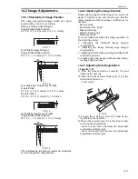
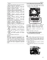
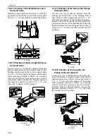
14.5.1 Adjusting the Height of the
Charging Wire
0010-9325
T-14-2
MEMO:
The height (position) of the primary and transfer
charging wires may be adjusted by turning the
screw found at the rear of the charging assembly.
A full turn of the screw changes the position of
the charging wire by about 0.7 mm.
14.6 Fixing System
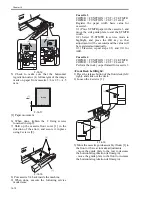
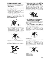
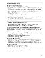
14.6.1 Adjusting the Lower Roller
Pressure (nip)
0010-9324
The nip width must be as indicated in figure; if
not, adjust it using the pressure adjusting nut.
F-14-34
a and c are points 10 mm from both edges of pa-
per.
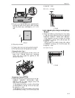
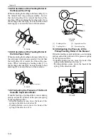
T-14-3
a. Generating Output for Nip Width
Measurement
Wait for 15 min after the copier ends its warm-up
period; make 20 A4 copies, and measure the nip.
1) Place A3 copy paper in the manual feed tray.
2) Make the following selections in service mode
to generate output:
COPIER > FUNCTION > FIXING > NIP-
CHK.
The A3 paper will be picked up, and a copy like
the one shown in figure will be delivered.
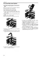
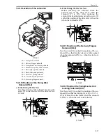
14.6.2 Points to Note When Mounting the
Fixing Heater
0010-9623
1. Do not touch the heater surface.
2. For both heaters, mount so that the side with
the longer heater harness is toward the front.
3. Viewing from the front of the fixing assembly,
mount the main heater on the right (for 200V
model, 1150 W; for 208V model, 1220 W; for
230V model, 1185 W) and the sub heater on the
left (for 200V model, 565 W; for 208V model,
600 W; for 230V model, 645 W).
4. Viewing from the rear, connect the right side of
the faston of the heater at the rear to the main
heater, and connect the top side to the sub
heater.
Height of the Fixing Inlet Guide
Height of charging wire
Primary
Pre-transfer
Separation
Transfer
7.5
- 0mm
+3mm
7.5
- 0mm
+3mm
13.6 ±0.3mm
No height adjusting
mechanism
17.0
0.2mm
15.5
0.2mm
9.0
0.2mm
Dimension
Measure with upper and lower
rollers fully heated
b
200 V: 9.0 -/+ 0.5 mm, 208/230 V:
10.0 -/+ 0.5 mm
| a-c |
0.5 mm or less
Feed
direction
c
a
Middle
of paper
b
A3 paper
Содержание IMAGERUNNER 7095 PRINTER
Страница 20: ...Chapter 1 Introduction...
Страница 46: ...Chapter 2 Installation...
Страница 88: ...Chapter 3 Basic Operation...
Страница 94: ...Chapter 4 Main Controller...
Страница 116: ...Chapter 5 Original Exposure System...
Страница 165: ...Laser Exposure Chapter 6...
Страница 175: ...Chapter 7 Image Formation...
Страница 180: ...Chapter 7 7 3 7 3 Basic Sequence 7 3 1 Basic Sequence 0010 8038 F 7 3 ON ON WMUPR WMUP STBY OFF 100msec...
Страница 231: ...Chapter 8 Pickup Feeding System...
Страница 287: ...Chapter 9 Fixing System...
Страница 312: ...Chapter 10 External and Controls...
Страница 346: ...Chapter 11 MEAP...
Страница 350: ...Chapter 12 RDS...
Страница 360: ...Chapter 13 Maintenance Inspection...
Страница 375: ...Chapter 14 Standards Adjustments...
Страница 407: ...Chapter 15 Correcting Faulty Images...
Страница 433: ...Chapter 16 Self Diagnosis...
Страница 460: ...Chapter 17 Service Mode...
Страница 559: ...Chapter 18 Upgrading...
Страница 583: ...Chapter 19 Service Tools...
Страница 584: ...Contents Contents 19 1 Service Tools 19 1 19 1 1 Special Tools Table 19 1 19 1 2 Solvents Oils 19 2...
Страница 588: ...APPENDIX...
Страница 615: ......


