


Chapter 14
14-23
2. Making Use of Non-Auto Control Mode
If a fault occurs in images, use the mode to find
out if the cause is on the input side or output side
of the microprocessor on the DC controller PCB.
In non-auto control mode, if the fault is corrected
somewhat, you may suspect the potential meas-
urement unit or the DC controller PCB.
c. Zero-Level Check
One way of finding out if the surface potential
control circuit is good or not is to use a zero-level
check.
MEMO:
A zero-level check is made to see if the micro-
processor registers 0 V when the surface potential
of the drum is 0 V.
Using the result of the check, you can find out if
the microprocessor on the DC controller PCB or
the measurement unit is good or not; a zero-level
check may take either of the following two meth-
ods:
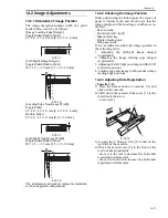
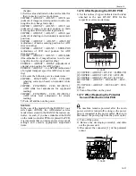
1. Method 1
1) Turn off the power switch.
2) Short the connectors J522-1 and -2 on the DC
controller PCB with a jumper wire, and
disconnect the connector J3 of the potential
control PCB.
F-14-44
3) Fit the door switch actuator into the door
switch assembly, and turn on the power switch.
4) Make the following selections in service mode,
and check to see if the reading is between 0 and
30 during initial rotation: COPIER>
DISPLAY> DPOT> DPOT-K.
MEMO:
If the reading is not as indicated, you may suspect
a fault in the DC controller PCB.
5) Turn off the power switch, and detach the door
switch actuator.
6) Detach the jumper wire from the DC controller
PCB.
7) Connect the connector to J3 of the potential
control PCB.
8) Turn on the power switch.
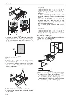
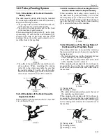
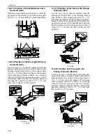
2. Method 2
1) Turn off the power switch.
2) Remove the developing assembly, and slide
out the process unit.
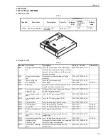
3) Disconnect the connector [1] of the potential
sensor.
F-14-45
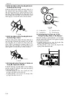
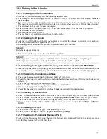
4) Remove the 2 screws [1], and detach the
potential sensor support plate [2].
F-14-46
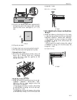
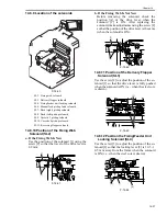
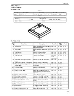
5) Put back the developing assembly and the
process unit.
6) Connect the connector [1] of the potential
sensor.
F-14-47
7) Fit the potential sensor checker electrode
(FY9-3041) [2] to the potential sensor [1].
When fitting the checker electrode to the poten-
tial sensor, be sure that the magnet of the checker
electrode will not come into contact with the po-
tential sensor cover.
Connector
J3
J522
[1]
[2]
[1]
[1]
Содержание IMAGERUNNER 7095 PRINTER
Страница 20: ...Chapter 1 Introduction...
Страница 46: ...Chapter 2 Installation...
Страница 88: ...Chapter 3 Basic Operation...
Страница 94: ...Chapter 4 Main Controller...
Страница 116: ...Chapter 5 Original Exposure System...
Страница 165: ...Laser Exposure Chapter 6...
Страница 175: ...Chapter 7 Image Formation...
Страница 180: ...Chapter 7 7 3 7 3 Basic Sequence 7 3 1 Basic Sequence 0010 8038 F 7 3 ON ON WMUPR WMUP STBY OFF 100msec...
Страница 231: ...Chapter 8 Pickup Feeding System...
Страница 287: ...Chapter 9 Fixing System...
Страница 312: ...Chapter 10 External and Controls...
Страница 346: ...Chapter 11 MEAP...
Страница 350: ...Chapter 12 RDS...
Страница 360: ...Chapter 13 Maintenance Inspection...
Страница 375: ...Chapter 14 Standards Adjustments...
Страница 407: ...Chapter 15 Correcting Faulty Images...
Страница 433: ...Chapter 16 Self Diagnosis...
Страница 460: ...Chapter 17 Service Mode...
Страница 559: ...Chapter 18 Upgrading...
Страница 583: ...Chapter 19 Service Tools...
Страница 584: ...Contents Contents 19 1 Service Tools 19 1 19 1 1 Special Tools Table 19 1 19 1 2 Solvents Oils 19 2...
Страница 588: ...APPENDIX...
Страница 615: ......


