


Chapter 7
7-22
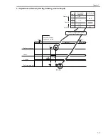
7.7.4 Controlling the Developing Bias
0010-8065
The following items are associated with the developing bias control system:
[1] DC bias constant voltage control
[2] AC bias constant voltage control
F-7-29
DC controller PCB
J510A
J723
J721
3
4
5
6
7
8
9
10
11
12
13
14
15
16
17
18
1
2
3
4
5
6
7
8
9
10
11
12
13
14
15
16
0 V
24 VH
24 VH
HVDC_REMOTE
DEV_DC_CNTR
DEV_AC_ON
GND
GND
1 2 3 4
Relay PCB
Developing cylinder
J732
Voltage input between 0 and 12 V,
used to control the voltage level
of the developing DC bias.
500V
Image area
Non-image
area
The developing DC bias varies as follows
according to the potential of DEV_DC_CNTR:
3V
11V 12V
DEV_DC_CNTR
De
v
eloping DC bias
AC output: 1200 Vpp
When '1', high-voltage
output is ready.
When '1', the developing
AC bias is generated.
2
1
17
18
High-voltage DC PCB
Содержание IMAGERUNNER 7095 PRINTER
Страница 20: ...Chapter 1 Introduction...
Страница 46: ...Chapter 2 Installation...
Страница 88: ...Chapter 3 Basic Operation...
Страница 94: ...Chapter 4 Main Controller...
Страница 116: ...Chapter 5 Original Exposure System...
Страница 165: ...Laser Exposure Chapter 6...
Страница 175: ...Chapter 7 Image Formation...
Страница 180: ...Chapter 7 7 3 7 3 Basic Sequence 7 3 1 Basic Sequence 0010 8038 F 7 3 ON ON WMUPR WMUP STBY OFF 100msec...
Страница 231: ...Chapter 8 Pickup Feeding System...
Страница 287: ...Chapter 9 Fixing System...
Страница 312: ...Chapter 10 External and Controls...
Страница 346: ...Chapter 11 MEAP...
Страница 350: ...Chapter 12 RDS...
Страница 360: ...Chapter 13 Maintenance Inspection...
Страница 375: ...Chapter 14 Standards Adjustments...
Страница 407: ...Chapter 15 Correcting Faulty Images...
Страница 433: ...Chapter 16 Self Diagnosis...
Страница 460: ...Chapter 17 Service Mode...
Страница 559: ...Chapter 18 Upgrading...
Страница 583: ...Chapter 19 Service Tools...
Страница 584: ...Contents Contents 19 1 Service Tools 19 1 19 1 1 Special Tools Table 19 1 19 1 2 Solvents Oils 19 2...
Страница 588: ...APPENDIX...
Страница 615: ......