


10
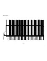
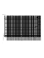
General Circuit Diagram (4/20)
F-2-4
A
4
3
2
C
B
D
E
F
A
C
B
D
E
F
7
6
5
1
4
3
2
7
8
8
6
5
1
Transceiver PCB
PS56
MSW7
M8
DP1
PS58
PS47
FM20
Upper right cover
open/closed sensor
Vertical path roller 1
paper sensor
Separation heat
discharge fan
Manual feed tray
cover open/closed
sensor
Primary charging
wire cleaner motor
Front cover
open/closed
detecting switch
Drum surface potential
measurement
DC controller PCB
Potential control PCB
(4/20)
Содержание IMAGERUNNER 7095 PRINTER
Страница 20: ...Chapter 1 Introduction...
Страница 46: ...Chapter 2 Installation...
Страница 88: ...Chapter 3 Basic Operation...
Страница 94: ...Chapter 4 Main Controller...
Страница 116: ...Chapter 5 Original Exposure System...
Страница 165: ...Laser Exposure Chapter 6...
Страница 175: ...Chapter 7 Image Formation...
Страница 180: ...Chapter 7 7 3 7 3 Basic Sequence 7 3 1 Basic Sequence 0010 8038 F 7 3 ON ON WMUPR WMUP STBY OFF 100msec...
Страница 231: ...Chapter 8 Pickup Feeding System...
Страница 287: ...Chapter 9 Fixing System...
Страница 312: ...Chapter 10 External and Controls...
Страница 346: ...Chapter 11 MEAP...
Страница 350: ...Chapter 12 RDS...
Страница 360: ...Chapter 13 Maintenance Inspection...
Страница 375: ...Chapter 14 Standards Adjustments...
Страница 407: ...Chapter 15 Correcting Faulty Images...
Страница 433: ...Chapter 16 Self Diagnosis...
Страница 460: ...Chapter 17 Service Mode...
Страница 559: ...Chapter 18 Upgrading...
Страница 583: ...Chapter 19 Service Tools...
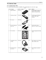
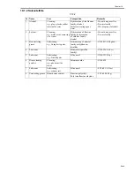
Страница 584: ...Contents Contents 19 1 Service Tools 19 1 19 1 1 Special Tools Table 19 1 19 1 2 Solvents Oils 19 2...
Страница 588: ...APPENDIX...
Страница 615: ......


