


Chapter 10
10-24
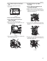
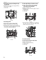
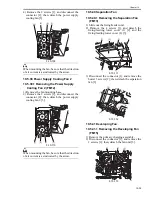
3) Slide out the high-voltage assembly [1] along
the rails on both sides to detach.
F-10-83
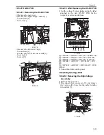
10.5.29 Motor Driver PCB
10.5.29.1 Before Starting the Work
0011-4918
1) Remove the main controller box cover [1].
- 10 screws [2]
F-10-84
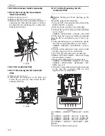
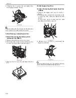
2) Remove the rear cover [1].
- 1 reader power supply cable [2]
- 8 screws [3]
F-10-85
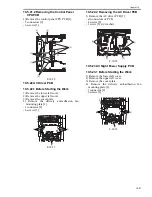
10.5.29.2 Removing the Fixing Inlet
Sensor Lift Motor Driver PCB
0011-4919
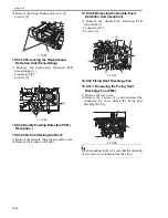
1) Remove the fixing inlet sensor lift motor driver
PCB [1].
- 2 connectors [2]
- 4 screws [3]
F-10-86
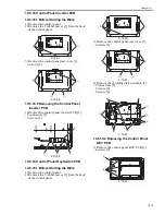
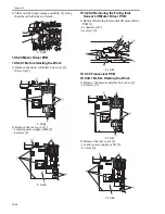
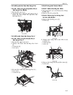
10.5.30 Transceiver PCB
10.5.30.1 Before Starting the Work
0011-4913
1) Remove the main controller box cover [1].
- 10 screws [2]
F-10-87
2) Remove the rear cover [1].
- 1 reader power supply cable [2]
- 8 crews [3]
F-10-88
[2]
[1]
[2]
[2]
[2]
[2]
[3]
[3]
[3]
[1]
[3]
[3]
[3]
[1]
[2]
[2]
[1]
[2]
[2]
[2]
[2]
[3]
[3]
[3]
[1]
Содержание IMAGERUNNER 7095 PRINTER
Страница 20: ...Chapter 1 Introduction...
Страница 46: ...Chapter 2 Installation...
Страница 88: ...Chapter 3 Basic Operation...
Страница 94: ...Chapter 4 Main Controller...
Страница 116: ...Chapter 5 Original Exposure System...
Страница 165: ...Laser Exposure Chapter 6...
Страница 175: ...Chapter 7 Image Formation...
Страница 180: ...Chapter 7 7 3 7 3 Basic Sequence 7 3 1 Basic Sequence 0010 8038 F 7 3 ON ON WMUPR WMUP STBY OFF 100msec...
Страница 231: ...Chapter 8 Pickup Feeding System...
Страница 287: ...Chapter 9 Fixing System...
Страница 312: ...Chapter 10 External and Controls...
Страница 346: ...Chapter 11 MEAP...
Страница 350: ...Chapter 12 RDS...
Страница 360: ...Chapter 13 Maintenance Inspection...
Страница 375: ...Chapter 14 Standards Adjustments...
Страница 407: ...Chapter 15 Correcting Faulty Images...
Страница 433: ...Chapter 16 Self Diagnosis...
Страница 460: ...Chapter 17 Service Mode...
Страница 559: ...Chapter 18 Upgrading...
Страница 583: ...Chapter 19 Service Tools...
Страница 584: ...Contents Contents 19 1 Service Tools 19 1 19 1 1 Special Tools Table 19 1 19 1 2 Solvents Oils 19 2...
Страница 588: ...APPENDIX...
Страница 615: ......


