


Chapter 17
17-19
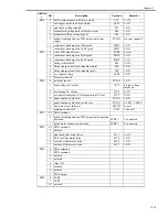
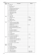
P014
0
buffer inside magnet roller drive clutch
CL1
1: ON
1
sub hopper inside toner feed clutch
CL23
1: ON
2
right deck pickup solenoid
SL7
1: ON
3
manual feed pickup latch solenoid (return)
SL6
1: ON
4
manual feed latch solenoid (pull)
SL6
1: ON
5
double-feeding detection PCB (reception) power
supply
PCB33
0: power supplied
6
reader heat discharge fan 1 full speed
FM21
1: ON
7
reader heat discharge fan 1 half speed
FM21
1: ON
P015
0
video PCB manual reset
PCB3
0: reset
1
reader heat discharge fan 2 full speed
FM18
1: ON
2
reader heat discharge fan 2 half speed
FM18
1: ON
3
fixing web solenoid
SL2
1: ON
4
fixing transport unit lock solenoid (return)
SL4
0: ON
5
fixing transport unit lock solenoid (pull)
SL4
1: ON
6
pre-exposure lamp
LED1
1: ON
7
for factory check
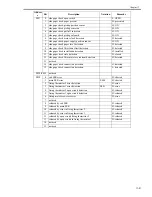
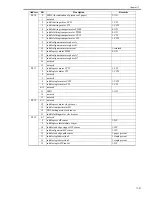
P016
0
potential sensor
PCB19
1: ON
1
high-voltage DC output
HVT
0: high-voltage
output on
2
developing AC output
HVT
0: ON
3
pre-transfer charging AC bias/separation AC bias
HVT
0: ON
4
paper transport guide bias
PCB11
0: ON
5
paper transport guide bias switchover
PCB11
0: 200V 1: 600V
6
waste toner case full reset
MSW2
0: reset
7
main power shut-off
SW1
1: shut-off
P017
0-5 DDI command
6
double-feeding detection PCB (reception) connection
detection
PCB33
1: connected
7
bottle motor connection detection
PCB23
0: connected
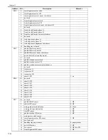
P018
0-2 DDI command
3
not used
4
right deck lifter motor drive
M13
1: ON
5
left deck lifter motor drive
M14
1: ON
6
cassette 3 lifter motor drive
M16
1: ON
7
cassette 4 lifter motor drive
M17
1: ON
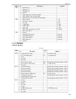
P019
0
DDI command
1
DDI command
2
not used
3
not used
4
relay ON
5
not used
6
not used
7
PTOP output
P020
0
LED2
1
LED1
2-7 not used
Addres
s
Bit
Description
Notation
Remarks
Содержание IMAGERUNNER 7095 PRINTER
Страница 20: ...Chapter 1 Introduction...
Страница 46: ...Chapter 2 Installation...
Страница 88: ...Chapter 3 Basic Operation...
Страница 94: ...Chapter 4 Main Controller...
Страница 116: ...Chapter 5 Original Exposure System...
Страница 165: ...Laser Exposure Chapter 6...
Страница 175: ...Chapter 7 Image Formation...
Страница 180: ...Chapter 7 7 3 7 3 Basic Sequence 7 3 1 Basic Sequence 0010 8038 F 7 3 ON ON WMUPR WMUP STBY OFF 100msec...
Страница 231: ...Chapter 8 Pickup Feeding System...
Страница 287: ...Chapter 9 Fixing System...
Страница 312: ...Chapter 10 External and Controls...
Страница 346: ...Chapter 11 MEAP...
Страница 350: ...Chapter 12 RDS...
Страница 360: ...Chapter 13 Maintenance Inspection...
Страница 375: ...Chapter 14 Standards Adjustments...
Страница 407: ...Chapter 15 Correcting Faulty Images...
Страница 433: ...Chapter 16 Self Diagnosis...
Страница 460: ...Chapter 17 Service Mode...
Страница 559: ...Chapter 18 Upgrading...
Страница 583: ...Chapter 19 Service Tools...
Страница 584: ...Contents Contents 19 1 Service Tools 19 1 19 1 1 Special Tools Table 19 1 19 1 2 Solvents Oils 19 2...
Страница 588: ...APPENDIX...
Страница 615: ......


