


Chapter 14
14-21
the data.
3) Set the values indicated on the service label for
their respective service mode items.
COPIER > ADJUST > ADJ-XY > ADJ-X (ad-
justment of image read start position in sub scan-
ning direction; image lead edge)
COPIER > ADJUST > ADJ-XY > ADJ-Y (ad-
justment of image read start position in main
scanning direction; horizontal registration)
COPIER > ADJUST > ADJ-XY > ADJ-S (ad-
justment of shading correction data measurement
position)
COPIER > ADJUST > ADJ-XY > ADJ-Y-DF
(adjustment of main scanning position for ADF
stream reading)
COPIER > ADJUST > ADJ-XY > STRD-POS
(adjustment of CCD read position for ADF
stream reading)
COPIER > ADJUST > ADJ-XY > ADJ-X-MG
(fine-adjustment of magnification in sub scan-
ning direction for copyboard reading)
FEEDER > ADJUST > DOCST (adjustment of
original stop position for ADF pickup)
FEEDER > ADJUST > LA-SPEED (adjustment
of original transport speed for ADF stream read-
ing)
4) Execute the following service mode items:
COPIER> FUNCTION> CCD> CCD-ADJ
(shading correction based on standard white
plate)
COPIER> FUNCTION> CCD> DF-WLVL1
(ADF white level adjustment; for copyboard
reading)
COPIER> FUNCTION> CCD> DF-WLVL2
(ADF white level adjustment; for stream
reading)
5) Turn off and then on the power.
MEMO:
In the case of the model with the DADF-M1 (out-
side Japan: iR7086), the ADF-related service
mode data is stored in the RAM of the reader con-
troller. As such, if you have initialized the RAM
on the reader controller PCB or replaced the PCB,
it is important that you newly enter service mode
settings and execute appropriate adjustment
items.
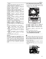
14.7.6 After Replacing the HV-DC PCB
0010-9330
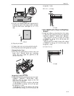
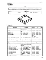
1) Set the values (5 types) indicated on the label
attached to the new HV-DC PCB for the
respective service mode items:
F-14-38
[1] COPIER > ADJUST > HV-TR > H-PRE-TR
[2] COPIER > ADJUST > HV-TR > HVT-TR
[3] COPIER > ADJUST > HV-SP > HVT-SP
[4] COPIER > ADJUST > DEVELOP > HVT-
DE
[5] COPIER > ADJUST > DEVELOP > OFF-
SETAC
2) Turn off and then on the power.
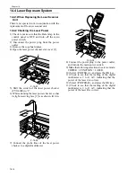
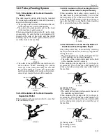
14.7.7 When Replacing the Potential
Sensor/Potential Control PCB
0010-9331
The machine remains powered after the main
power switch is turned off as long as the power
plug is connected to the power outlet. Be sure to
disconnect the power plug from the power outlet.
1) Turn off the power.
2) Remove the developing assembly, and slide
out the process unit.
3) Disconnect the connector [1] of the potential
sensor.
F-14-39
H+04+05+05+01+24
[1] [2] [3] [4] [5]
[1]
Содержание IMAGERUNNER 7095 PRINTER
Страница 20: ...Chapter 1 Introduction...
Страница 46: ...Chapter 2 Installation...
Страница 88: ...Chapter 3 Basic Operation...
Страница 94: ...Chapter 4 Main Controller...
Страница 116: ...Chapter 5 Original Exposure System...
Страница 165: ...Laser Exposure Chapter 6...
Страница 175: ...Chapter 7 Image Formation...
Страница 180: ...Chapter 7 7 3 7 3 Basic Sequence 7 3 1 Basic Sequence 0010 8038 F 7 3 ON ON WMUPR WMUP STBY OFF 100msec...
Страница 231: ...Chapter 8 Pickup Feeding System...
Страница 287: ...Chapter 9 Fixing System...
Страница 312: ...Chapter 10 External and Controls...
Страница 346: ...Chapter 11 MEAP...
Страница 350: ...Chapter 12 RDS...
Страница 360: ...Chapter 13 Maintenance Inspection...
Страница 375: ...Chapter 14 Standards Adjustments...
Страница 407: ...Chapter 15 Correcting Faulty Images...
Страница 433: ...Chapter 16 Self Diagnosis...
Страница 460: ...Chapter 17 Service Mode...
Страница 559: ...Chapter 18 Upgrading...
Страница 583: ...Chapter 19 Service Tools...
Страница 584: ...Contents Contents 19 1 Service Tools 19 1 19 1 1 Special Tools Table 19 1 19 1 2 Solvents Oils 19 2...
Страница 588: ...APPENDIX...
Страница 615: ......


