


Contents
Contents
14.1
Image Adjustment Basic Procedure
........................................................................................................ 14- 1
14.1.1
Making Pre-Checks
............................................................................................................................. 14- 1
14.1.2
Making Checks on the Printer Side (Checking the Images)
......................................................... 14- 1
14.1.3
Making Checks on the Printer Side (Checking the Density Slope)
.............................................. 14- 2
14.1.4
Making Checks on the Printer Side (Checking the Solid Black Density)
.................................... 14- 3
14.1.5
Making Checks on the Printer Side (Checking for fogging)
.......................................................... 14- 4
14.1.6
Making Checks on the Printer Side (Checking Halftone Density)
................................................ 14- 4
14.1.7
Making Checks on the Reader Unit
.................................................................................................. 14- 5
14.1.8
Potential Control System Conversion Table
.................................................................................... 14- 7
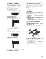
14.2
Image Adjustments
................................................................................................................................... 14- 11
14.2.1
Standards of Image Position
............................................................................................................ 14- 11
14.2.2
Checking the Image Position
........................................................................................................... 14- 11
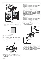
14.2.3
Adjusting Side Registration
.............................................................................................................. 14- 11
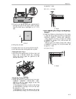
14.2.4
Adjusting the Image Leading Edge Margin
.................................................................................... 14- 13
14.2.5
Adjusting the Left/Right Non-Image Width
.................................................................................... 14- 14
14.2.6
Adjusting the Leading Edge Non-Image Width
............................................................................. 14- 14
14.3
Scanning System
...................................................................................................................................... 14- 14
14.3.1
When Replacing Components of the Scanning System
.............................................................. 14- 14
14.3.2
When Replacing Components of the Scanning System
.............................................................. 14- 14
14.3.3
Adjusting the Position of the No. 1/No. 2 Mirror Base
................................................................. 14- 14
14.4
Laser Exposure System
........................................................................................................................... 14- 16
14.4.1
When Replacing the Laser Scanner Unit
....................................................................................... 14- 16
14.4.2
Checking the Laser Power
............................................................................................................... 14- 16
14.5
Image Formation System
........................................................................................................................ 14- 17
14.5.1
Adjusting the Height of the Charging Wire
.................................................................................... 14- 17
14.6
Fixing System
............................................................................................................................................ 14- 17
14.6.1
Adjusting the Lower Roller Pressure (nip)
..................................................................................... 14- 17
14.6.2
Points to Note When Mounting the Fixing Heater
........................................................................ 14- 17
14.7
Electrical Components
............................................................................................................................. 14- 18
14.7.1
After Replacing the Hard Disk
......................................................................................................... 14- 18
14.7.2
After Replacing the Main Controller
................................................................................................ 14- 18
14.7.3
After Replacing the DC Controller PCB
......................................................................................... 14- 20
14.7.4
After Replacing the Reader Controller PCB
.................................................................................. 14- 20
14.7.5
After Replacing the Reader Controller PCB
.................................................................................. 14- 20
14.7.6
After Replacing the HV-DC PCB
..................................................................................................... 14- 21
14.7.7
When Replacing the Potential Sensor/Potential Control PCB
.................................................... 14- 21
14.7.8
Checking the Surface Potential Control System
........................................................................... 14- 22
14.7.9
Checking the Environment Sensor
................................................................................................. 14- 24
14.8
Pickup/Feeding System
........................................................................................................................... 14- 25
14.8.1
Orientation of the Deck/Cassette Pickup Roller
............................................................................ 14- 25
14.8.2
Orientation of the Deck/Cassette Separation Roller
.................................................................... 14- 25
14.8.3
Orientation of the Feeding Roller of the Deck/Cassette Pickup Assembly
.............................. 14- 25
14.8.4
Orientation of the Pickup Roller of the Manual Feed Tray/Side Paper
..................................... 14- 25
14.8.5
Orientation of the Feeding Roller of the Manual Feed Tray
........................................................ 14- 26
Содержание IMAGERUNNER 7095 PRINTER
Страница 20: ...Chapter 1 Introduction...
Страница 46: ...Chapter 2 Installation...
Страница 88: ...Chapter 3 Basic Operation...
Страница 94: ...Chapter 4 Main Controller...
Страница 116: ...Chapter 5 Original Exposure System...
Страница 165: ...Laser Exposure Chapter 6...
Страница 175: ...Chapter 7 Image Formation...
Страница 180: ...Chapter 7 7 3 7 3 Basic Sequence 7 3 1 Basic Sequence 0010 8038 F 7 3 ON ON WMUPR WMUP STBY OFF 100msec...
Страница 231: ...Chapter 8 Pickup Feeding System...
Страница 287: ...Chapter 9 Fixing System...
Страница 312: ...Chapter 10 External and Controls...
Страница 346: ...Chapter 11 MEAP...
Страница 350: ...Chapter 12 RDS...
Страница 360: ...Chapter 13 Maintenance Inspection...
Страница 375: ...Chapter 14 Standards Adjustments...
Страница 407: ...Chapter 15 Correcting Faulty Images...
Страница 433: ...Chapter 16 Self Diagnosis...
Страница 460: ...Chapter 17 Service Mode...
Страница 559: ...Chapter 18 Upgrading...
Страница 583: ...Chapter 19 Service Tools...
Страница 584: ...Contents Contents 19 1 Service Tools 19 1 19 1 1 Special Tools Table 19 1 19 1 2 Solvents Oils 19 2...
Страница 588: ...APPENDIX...
Страница 615: ......


