


Chapter 17
17-43
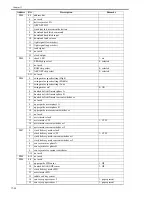
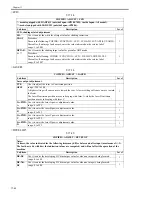
<HV-TR>
T-17-25
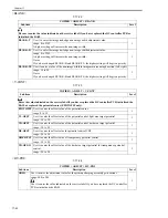
COPIER > ADJUST > HV-TR
Sub item
Description
Level
Notes:
At times, the indicated value for the fogging items may differ before and after input (maximum of +/-3). The
fact has to do with the way indicated values are computed, and will not affect the operation of the machine.
TR-N1
Use it to enter the output adjustment value of the transfer charging current. (simplex mode,
plain paper; or 1st side of double-sided print)
1
range: -650 to 0
Be sure to enter the value indicated on the service label if you have replaced the DC
controller PCB or initialized the RAM.
TR-N2
Use it to enter the output adjustment value of the transfer charging current. (plain paper, 2nd
side of double-sided print)
1
range: -650 to 0
Be sure to enter the value indicated on the service label if you have replaced the DC
controller PCB or initialized the RAM.
PRE-TR
Use it to enter the output adjustment value of the pre-transfer charging current.
1
range: 0 to 300
Be sure to enter the value indicated on the service label if you have replaced the DC
controller PCB or initialized the RAM.
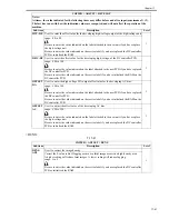
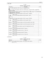
HVT-TR
Use it to enter the offset value of the transfer high-voltage output for the high-voltage unit.
1
range: -100 to 100
Be sure to enter the value indicated on the label attached to the new unit if you have replace
the high-voltage unit.
Be sure to enter the value indicated on the service label if you have replaced the DC
controller PCB or initialized the RAM.
H-PRE-TR
Use it to enter the offset voltage of the pre-transfer output for the high-voltage unit.
1
range: -100 to 100
Be sure to enter the value indicated on the label attached to the new unit if you have replace
the high-voltage unit.
Be sure to enter the value indicated on the service label if you have replaced the DC
controller PCB or initialized the RAM.
D-PRE-TR
Use it to enter the offset value of the pre-transfer high-voltage output or the DC controller
PCB.
1
range: -100 to 100
Be sure to enter the value indicated on the label attached to the new PCB if you have
replaced the DC controller PCB.
Be sure to enter the value indicated on the service label if you have initialized the RAM on
the DC controller PCB.
D-HV-TR
Use it to enter the offset value of the transfer high-voltage output for the DC controller PCB.
1
range: -100 to 100
Be sure to enter the value indicated on the label attached to the new PCB if you have
replaced the DC controller PCB.
Be sure to enter the value indicated on the service label if you have initialized the RAM on
the DC controller PCB.
Содержание IMAGERUNNER 7095 PRINTER
Страница 20: ...Chapter 1 Introduction...
Страница 46: ...Chapter 2 Installation...
Страница 88: ...Chapter 3 Basic Operation...
Страница 94: ...Chapter 4 Main Controller...
Страница 116: ...Chapter 5 Original Exposure System...
Страница 165: ...Laser Exposure Chapter 6...
Страница 175: ...Chapter 7 Image Formation...
Страница 180: ...Chapter 7 7 3 7 3 Basic Sequence 7 3 1 Basic Sequence 0010 8038 F 7 3 ON ON WMUPR WMUP STBY OFF 100msec...
Страница 231: ...Chapter 8 Pickup Feeding System...
Страница 287: ...Chapter 9 Fixing System...
Страница 312: ...Chapter 10 External and Controls...
Страница 346: ...Chapter 11 MEAP...
Страница 350: ...Chapter 12 RDS...
Страница 360: ...Chapter 13 Maintenance Inspection...
Страница 375: ...Chapter 14 Standards Adjustments...
Страница 407: ...Chapter 15 Correcting Faulty Images...
Страница 433: ...Chapter 16 Self Diagnosis...
Страница 460: ...Chapter 17 Service Mode...
Страница 559: ...Chapter 18 Upgrading...
Страница 583: ...Chapter 19 Service Tools...
Страница 584: ...Contents Contents 19 1 Service Tools 19 1 19 1 1 Special Tools Table 19 1 19 1 2 Solvents Oils 19 2...
Страница 588: ...APPENDIX...
Страница 615: ......


