


Chapter 17
17-42
<BLANK>
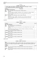
T-17-22
<V-CONT>
T-17-23
<HV-PRI>
T-17-24
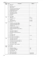
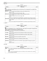
COPIER > ADJUST > BLANK
Sub item
Description
Level
Be sure to enter the value indicated on the service label if you have replaced the DC controller PCB or
initialized the RAM.
BLANK-T
Use it to enter the image lead edge non-image width adjustment value.
1
range: 0 to 2362
A higher setting will increase the non-image width.
BLANK-B
Use it to enter the image trail edge non-image width adjustment value.
1
range: 0 to 2362
A higher setting will increase the non-image width.
Notes:
If you have changed BLANK-B and BLANK-TE, the higher setting will be given priority.
BLANK-TE
Use it to enter a value of the non-image width in image main scanning direction (left, right).
1
range: 10 to 50
Notes:
If you have changed BLANK-B and BLANK-TE, the higher setting will be given priority.
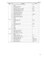
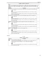
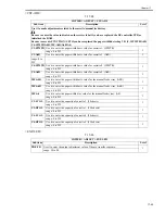
COPIER > ADJUST > V-CONT
Sub item
Description
Level
Enter the value indicated on the service label if you have replaced the DC controller PCB, initialized the
RAM, or replaced the potential sensor (EPOTOFST only).
EPOTOFST
Use it to enter the offset value of the potential sensor.
1
range: 0 to 30
VL-OFST
Use it to enter the offset value of the potential control light area target potential.
1
range: -50 to 50
VD-OFST
Use it to enter the offset value of the potential control dark area target potential.
1
range: -50 to 50
DE-OFST
Use it to enter the offset value for potential control VDC.
1
range: -50 to 50
OHP-OFST
Use it to enter the offset value of transparency potential control.
1
range: -50 to 50
VD-OFS-O
Use it to enter the offset value of the dark area target potential for transparency potential
control.
1
range: -50 to 50
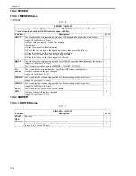
COPIER > ADJUST > HV-PRI
Sub item
Description
Level
GRID
Use it to enter the adjustment value for the primary charging assembly grid current.
1
range: 400 to 900
Use it to enter the value indicated on the service label if you have replaced the DC controller
PCB or initialized the RAM.
Содержание IMAGERUNNER 7095 PRINTER
Страница 20: ...Chapter 1 Introduction...
Страница 46: ...Chapter 2 Installation...
Страница 88: ...Chapter 3 Basic Operation...
Страница 94: ...Chapter 4 Main Controller...
Страница 116: ...Chapter 5 Original Exposure System...
Страница 165: ...Laser Exposure Chapter 6...
Страница 175: ...Chapter 7 Image Formation...
Страница 180: ...Chapter 7 7 3 7 3 Basic Sequence 7 3 1 Basic Sequence 0010 8038 F 7 3 ON ON WMUPR WMUP STBY OFF 100msec...
Страница 231: ...Chapter 8 Pickup Feeding System...
Страница 287: ...Chapter 9 Fixing System...
Страница 312: ...Chapter 10 External and Controls...
Страница 346: ...Chapter 11 MEAP...
Страница 350: ...Chapter 12 RDS...
Страница 360: ...Chapter 13 Maintenance Inspection...
Страница 375: ...Chapter 14 Standards Adjustments...
Страница 407: ...Chapter 15 Correcting Faulty Images...
Страница 433: ...Chapter 16 Self Diagnosis...
Страница 460: ...Chapter 17 Service Mode...
Страница 559: ...Chapter 18 Upgrading...
Страница 583: ...Chapter 19 Service Tools...
Страница 584: ...Contents Contents 19 1 Service Tools 19 1 19 1 1 Special Tools Table 19 1 19 1 2 Solvents Oils 19 2...
Страница 588: ...APPENDIX...
Страница 615: ......


