SmartPAC 2 with WPC 2000 Integration User Manual
1128600
Program Mode
5-25
Setting Sensor Stop Type
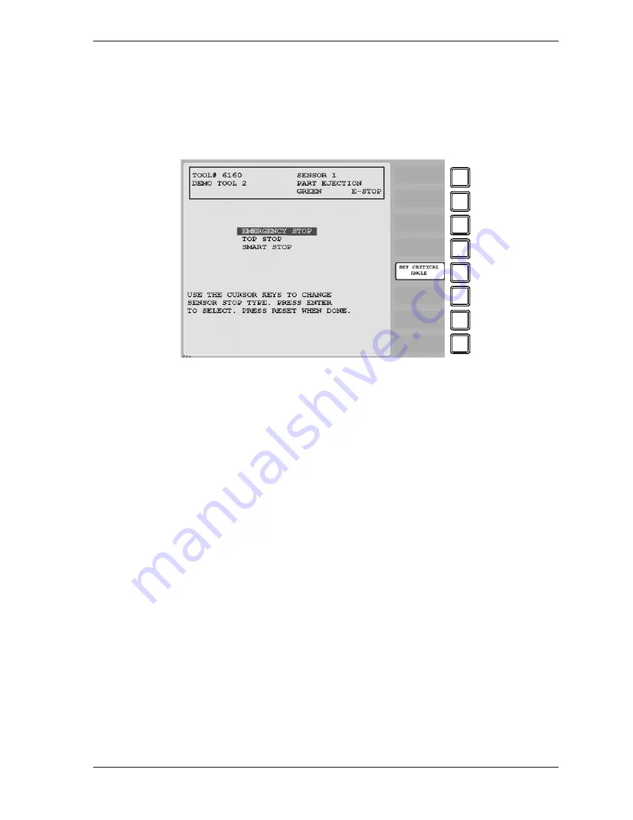
When you select a sensor type, the Sensor Stop Type screen, shown in Figure 5-26, displays.
The Sensor Stop Type screen allows you to specify how the press is to be stopped when the
die protection sensor detects a fault.
You can select one of three Stop Type settings for the sensor: emergency stop, top stop, or
smart stop. The three Stop Type options are described below.
•
Emergency Stop
(E-Stop). SmartPAC 2 stops the press as soon as a sensor fault is
detected. You should use this setting for any die-threatening event that occurs before the
critical angle, the point in the crankshaft rotation after which a stop signal to the press
cannot prevent the die from closing. A typical Emergency Stop application is a sensor that
monitors part ejection on the upstroke. Setting this sensor to an Emergency Stop ensures
that the ram will stop on the next stroke before the die closes.
•
Top Stop
. SmartPAC 2 stops the press at the top of its stroke after a sensor fault is
detected. You should use this setting for events that do not threaten the die or that occur
between the critical angle and bottom dead center (BDC). A typical Top Stop application is
a sensor that monitors a feed like a roll feed that takes place well into the downstroke.
Setting this sensor to a Top Stop ensures that the press does not stick on the bottom as a
result of a stop signal being sent just as the ram is about to contact the material.
•
Smart Stop
. SmartPAC 2 performs either a Top Stop or Emergency Stop depending on the
angle at which the sensor fault is detected. SmartPAC 2 top-stops the press if the fault is
detected after the critical angle but before bottom dead center (BDC). If the fault is
detected after BDC but before the critical angle, SmartPAC 2 performs an emergency stop.
A typical Smart Stop application is a sensor that monitors short feeds, which can occur
either before or after the critical angle. When you select SMART STOP as the stop type,
you must specify the critical angle.
Figure 5-26. Sensor Stop Type Screen
F1
F2
F3
F4
F5
F6
F7
F8
Summary of Contents for SmartPAC 2
Page 2: ......
Page 4: ......
Page 6: ......
Page 28: ...1128600 SmartPAC 2 with WPC 2000 Integration User Manual xxii Table of Contents ...
Page 44: ...1128600 SmartPAC 2 with WPC 2000 Integration User Manual 1 16 Introduction ...
Page 186: ...1128600 SmartPAC 2 with WPC 2000 Integration User Manual 3 26 Keyboard Displays Etc ...
Page 440: ...1128600 SmartPAC 2 with WPC 2000 Integration User Manual D 12 Updating SmartPAC 2 Firmware ...
Page 478: ...1128600 SmartPAC 2 with WPC 2000 Integration User Manual G 6 Replacing SmartPAC 2 PC Board ...
Page 548: ...1128600 SmartPAC 2 with WPC 2000 Integration User Manual GL 8 Glossary ...
Page 558: ...1128600 SmartPAC 2 with WPC 2000 Integration User Manual IN 10 Index ...
Page 560: ......
Page 562: ......
Page 564: ......
Page 566: ......
Page 568: ......
Page 570: ......
Page 572: ......
Page 574: ......
Page 576: ......
Page 577: ......
Page 578: ...APPROVALS SCALE C SIZE TITLE SHEET OF DRAWING NUMBER REV ...
Page 579: ...APPROVALS SCALE C SIZE TITLE SHEET OF DRAWING NUMBER REV ...
Page 580: ...APPROVALS SCALE C SIZE TITLE SHEET OF DRAWING NUMBER REV ...
Page 581: ...APPROVALS SCALE C SIZE TITLE SHEET OF DRAWING NUMBER REV ...
Page 582: ......
Page 583: ......
Page 584: ......
Page 585: ......
Page 586: ......
Page 587: ......
Page 588: ......
Page 589: ......
Page 590: ......
Page 591: ......
Page 592: ......
Page 593: ......
Page 594: ......
Page 595: ......
Page 596: ......
Page 597: ......
Page 598: ......
Page 599: ......
Page 600: ......
Page 601: ......
Page 602: ......
Page 603: ......
Page 604: ......


