3-4
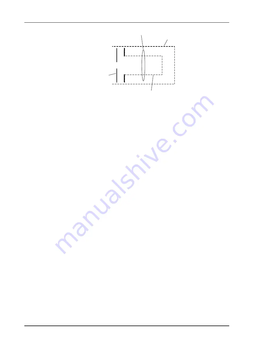
Ionizer
SRS Residual Gas Analyzer
Repeller
Anode grid
Filament
Focus plate
Figure 4 Ionizer Schematic
The filament is the source of the electrons used in ionizing the gas molecules. It operates
at a negative potential relative to ground and is resistively heated to incandescence with
an electrical current from the emission regulator. The thermionically emitted electrons are
accelerated towards the anode grid which is positively charged with reference to the
filament and ground. Because of the open (i.e. wire mesh) design of the anode grid cage,
most electrons do not strike the anode immediately, but pass through the cage where they
create ions through electron impact ionization. Electrons which do not strike a grid wire
or ionize any molecules, pass through the grid volume into the region between the anode
grid and the repeller. There they decelerate and re-accelerate back toward the grid
because of the electric field created between the repeller and the anode grid. Electrons
continue circulating in this fashion until they are collected by the grid or are lost by
recapture. The multiple passes increase the ionization efficiency of the electron current
relative to single pass configurations. Within the anode grid volume, ions are attracted to
the center by the negative potential produced by an increasing electron density toward the
center. Hence, the ions, once formed, tend to stay within the anode grid structure, and the
ion distribution is more localized along the axis. The ions formed within the anode grid
volume, are extracted from the ionizer by the electric field produced by the difference in
voltage bias between the anode grid and the focus plate. The focus plate is kept at a
negative potential (relative to ground) and its function is to draw the ions out of the anode
cage and focus them into the filter section. The repeller, which completely encloses the
ionizer, is biased negative relative to the filament and prevents the loss of electrons from
the ion source.
The Repeller Grid and the Focus Plate are only biased while the
filament is emitting electrons.
The technique of electron impact ionization requires low pressure for the efficient
production of electrons and the subsequent formation of ions. The ionizer is best suited
for operation in the high and ultrahigh vacuum range (10
-4
to 10
-14
Torr). Non-linearities
in the ion currents, attributed mostly to space charge effects, are to be expected at
pressures above 10
-5
Torr. Non-linearity effects can be minimized operating at reduced
electron emission current settings.
Parameter Settings
The parameters that affect the ionization efficiency of the ionizer are: electron energy, ion
energy, electron emission current and focusing voltage. The general principles by which
they affect the performance of the source are well understood.
Summary of Contents for RGA100
Page 4: ...SRS Residual Gas Analyzer iv...
Page 18: ...xviii Command List SRS Residual Gas Analyzer...
Page 46: ...2 14 Residual Gas Analysis Basics SRS Residual Gas Analyzer...
Page 66: ......
Page 78: ...4 12 Mass Filter Power supply SRS Residual Gas Analyzer...
Page 104: ......
Page 107: ...Programming the RGA Head 6 3 SRS Residual Gas Analyzer Error Byte Definitions 6 69...
Page 216: ...8 26 Quadrupole filter cleaning SRS Residual Gas Analyzer...
Page 246: ...11 2 SRS Residual Gas Analyzer...
Page 247: ......
Page 248: ......
Page 268: ...Appendix B SRS Residual Gas Analyzer 7...
Page 312: ...Appendix D SRS Residual Gas Analyzer 27...


