background image


Setting Conferences for Telepresence Mode (AVC CP)

Polycom®, Inc. 

173

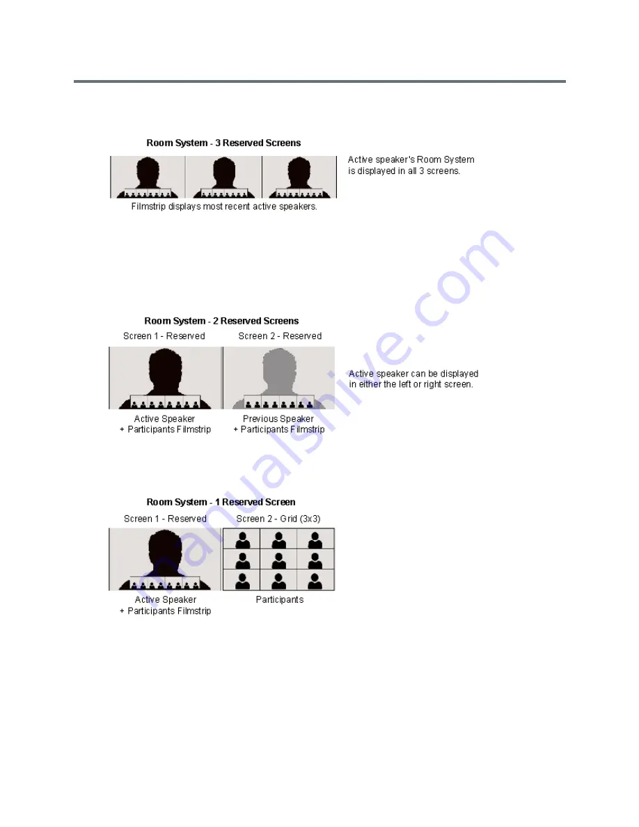
The layout below is used when the active speaker is using a 3-screen room system and the viewing 

endpoint is 3-screen endpoint.

If a two-screen Room System is displaying a active speaker using a one-camera endpoint, and a 

previous speaker also using a one-camera endpoint, the following layouts will be displayed on the 

Room System’s two screens. 
The layout below is used when the conference includes 4-screen rooms where both the active 

speaker and the previous active speaker are using single-screen endpoints.

The layout below is used when the conference includes 1, 2, and 3-screen rooms where the active 

speaker is using a single-screen endpoint.

Summary of Contents for RealPresence RMX 4000

Page 1: ...Version 8 5 January 2015 3725 74300 000B Administrator Guide RealPresence Collaboration Server RMX 1500 1800 2000 4000 ...

Page 2: ... open source software You may receive the open source software from Polycom up to three 3 years after the distribution date of the applicable product or software at a charge not greater than the cost to Polycom of shipping or distributing the software to you Disclaimer While Polycom uses reasonable efforts to include accurate and up to date information in this document Polycom makes no warranties ...

Page 3: ...sence Collaboration Server Supported Features 7 Software Prerequisites and Guidelines 9 Conferencing Modes Overview 11 AVC Conferencing 11 Continuous Presence CP Conferencing 11 Video Protocol Support in CP Conferences 13 Video Switching VSW Conferencing 13 Video Switching VSW Conferencing Guidelines 14 AVC Basic Conferencing Parameters 16 Supplemental Conferencing Features 17 SVC based Conferenci...

Page 4: ...AVC Based Conference Profiles 40 Defining AVC CP Conferencing Profiles 40 Additional Information for Setting CP Profiles 77 Gathering Phase 77 Gathering Phase Guidelines 78 Gathering Phase Duration 79 Enabling the Gathering Phase Display 80 Overlay Layouts 80 Guidelines for using the Overlay Layouts 81 Selecting the Overlay Layouts 82 Site Names Definition 83 Guidelines 84 Shorten the Site Name Di...

Page 5: ...olution Configuration for CP Conferences 116 Guidelines 116 Modifying the Resolution Configuration 116 Resolution Configuration Basic 118 Maximum CP Resolution Pane 118 Resolution Configuration Pane 118 Resolution Configuration Detailed 119 Sharpness and Motion 119 Resolution Configuration Sliders 120 Modifying the Resolution Configuration in MPMx Card Configuration Mode 122 Flag Settings 123 Sett...

Page 6: ... 136 H 264 Content Sharing Properties 136 Guidelines for Sharing Content Using H 264 HD 137 Content Sharing Related Issues 138 Sharing Content in Cascaded Environments 138 Sending Content to Legacy Endpoints 138 Guidelines for Sending Content to Legacy Endpoints 139 Content Display on Legacy Endpoints 139 Sending Content to Legacy Endpoints in Telepresence Mode 139 Exclusive Content Mode 140 Guide...

Page 7: ...Enabling Encryption at the Participant Level 161 Monitoring the Encryption Status 162 Setting Conferences for Telepresence Mode AVC CP 164 Collaboration Server Telepresence Mode Guidelines 164 System Level 164 Conference Level 164 Automatic Detection of Immersive Telepresence ITP Sites 165 Horizontal Striping 165 Cropping 166 Gathering Phase with ITP Room Systems 166 Aspect ratio for standard endp...

Page 8: ...188 Video Preview Guidelines 188 Workstation Requirements to Display Video Preview 189 Testing your Workstation 189 Previewing the Participant Video 190 Auto Scan and Customized Polling in Video Layout 192 Guidelines for Using Auto Scan and Customized Polling 192 Enabling the Auto Scan and Customized Polling 192 Enabling the Auto Scan 192 Customized Polling 193 Packet Loss Compensation LPR and DBA...

Page 9: ...cipant Audio Properties 217 Automatic Muting of Noisy Endpoints 218 Guidelines for Automatically Muting Noisy Endpoints 218 Automatic Muting of Noisy Endpoints 219 Automatic Muting of Noisy Endpoints at the Conference Level 219 Automatic Muting of Noisy Endpoints at the MCU Level 220 Permanent Conference 221 Guidelines 221 Enabling a Permanent Conference 222 Closed Captions 223 Closed Captions Gui...

Page 10: ...g Cascading 246 Creating the Cascade enabled Entry Queue 247 Creating the Dial out Cascaded Link 248 Enabling Cascaded Conferences without Password 250 Monitoring Star Cascaded Conferences 250 Creating the Dial out Link from a Conference Running on the MGC to the Conference Run ning on the RealPresence Collaboration Server 251 Cascading Conferences H 239 enabled MIH Topology 252 MIH Cascading Leve...

Page 11: ...lycom Distributed Media Application DMA 7000 290 Address Book 291 Viewing the Address Book 292 Displaying and Hiding the Group Members in the Navigation Pane 293 Participants List Pane Information 293 Displaying and Hiding the Address Book 294 Adding Participants from the Address Book 294 Adding Individual Participants from the Address Book to Conferences 294 Adding a Group from the Address Book t...

Page 12: ...g Reservations 316 System 316 Resources 316 Reservations 317 Using the Reservation Calendar 318 Toolbar Buttons 318 Reservations Views 319 Week View 319 Day View 319 Today View 320 List View 320 Changing the Calendar View 321 Scheduling Conferences Using the Reservation Calendar 323 Creating a New Reservation 323 Managing Reservations 329 Guidelines 329 Viewing and Modifying Reservations 329 Using...

Page 13: ...or Conference as a Template 358 Starting an Ongoing Conference From a Template 359 Starting an Operator Conference from a Template AVC Conferencing 360 Scheduling a Reservation From a Conference Template 361 Deleting a Conference Template 363 Exporting and Importing Conference Templates 363 Exporting Conference Templates 364 Exporting All Conference Templates from an MCU 364 Exporting Selected Con...

Page 14: ...ines 397 Creating and Connecting to a Conference 399 Creating a Conference 399 Connecting to a Conference 400 Collaboration Server Standalone Deployment 401 Collaboration Server and Polycom RealPresence DMA System Deployment 401 Polycom Solution Support 401 Conference and Participant Monitoring 402 General Monitoring 402 Multi Selection 403 Using the Chairperson Password for Filtering 403 Conferen...

Page 15: ...n a Conference IVR Service 457 Enabling the Recording in the Conference Profile 458 Dial Out Recording Link Encryption 460 Dial Out Recording Link Encryption Flag Setting 460 Dial Out Recording Link Settings 461 Managing the Recording Process 461 Recording Layout 462 Using the Collaboration Server Web Client to Manage the Recording Process 463 Using DTMF Codes to Manage the Recording Process 465 C...

Page 16: ...r RMX 1500 512 Media Redundancy on RealPresence Collaboration Server RMX 2000 4000 512 Media and Signaling Redundancy on RealPresence Collaboration Server RMX 1800 513 Signaling and Management Redundancy 514 Signaling and Management Redundancy on RealPresence Collaboration Server RMX 1500 514 Signaling and Management Redundancy on RealPresence Collaboration Server RMX 4000 515 Management Redundanc...

Page 17: ...lation 538 RealPresence Collaboration Server RMX 4000 Multiple Services Configuration 539 RealPresence Collaboration Server RMX 2000 Multiple Services Configuration 540 RealPresence Collaboration Server RMX 1800 Multiple Services Configuration 542 RealPresence Collaboration Server RMX 1500 Multiple Services Configuration 543 Collaboration Server Configuration 544 System Flags and License Settings ...

Page 18: ...r Entry Queue IVR Service as the Default Service 596 Modifying the Conference or Entry Queue IVR Service Properties 598 Replacing the Music File 599 Adding a Music File 599 Creating Audio Prompts and Video Slides 600 Recording an Audio Message 600 Defining the format settings for audio messages 600 Recording a new audio message 602 Creating a Welcome Video Slide 604 Inviting Participants using DTM...

Page 19: ...lows 624 IP Participants 624 Direct Dialing 624 Gateway IVR Dialing For IP Participants 627 Direct Dialing Using IP Addresses 628 Calling a SIP Endpoint in a Remote Domain 630 ISDN Participants 631 Dialing via Gateway IVR for ISDN Participants 631 Direct Dial in to Endpoints or DMA VMR using Automatically Generated Destination Numbers 632 Configuring the Gateway Components on the Collaboration Ser...

Page 20: ...er 652 Accessing the RMX Manager Application Installer Directly from the MCU 652 Downloading the Installation files from Polycom Support Site 653 Accessing the RMX Manager Installer from the Login screen 654 Installing the RMX Manager on Your Workstation 654 Installing the RMX Manager for Multi User Capability 656 Starting the RMX Manager Application 658 Connecting to the MCU 660 RMX Manager Main ...

Page 21: ...icipant Alerts 691 System Alerts 692 Participant Alerts 694 RMX Time 695 Altering the clock 695 Resource Management 697 Resource Capacity 697 MCU Capacities in CP Only Conferencing and SVC Only Conferencing 697 MCU Capacities in Mixed CP and SVC Conferencing 699 AVC Conferencing Video Switching Resource Capacity 700 Resource Usage in AVC CP Conferencing 701 AVC Conferencing Voice 701 Resource Capa...

Page 22: ...hreshold 712 SIP Dial in Busy Notification 713 Port Usage Gauges 714 System Information 716 SNMP Simple Network Management Protocol 717 MIBs Management Information Base 717 Traps 717 Guidelines 717 MIB Files 717 Private MIBs 717 Support for MIB II Sections 718 The Alarm MIB 718 H 341 MIB H 341 H 323 718 Standard MIBs 718 Unified MIB 719 Traps 721 Status Trap 722 RMX MIB entities that do not genera...

Page 23: ...nostic Files 745 Information Collector 747 Standard Security Mode 747 Ultra Secure Mode 748 Network Intrusion Detection System NIDS 748 Using the Information Collector 749 Step 1 Creating the Information Collector Compressed File 749 Step 2 Saving the Compressed File 750 Step 3 Viewing the Compressed File 751 Auditor 751 Auditor Files 751 Retrieving Auditor Files 752 Auditor File Viewer 753 Audit ...

Page 24: ...815 Modifying the Ultra Secure Mode System Flag Value 815 System Flags affected by Ultra Secure Mode 816 Certificate Management 818 PKI Public Key Infrastructure 818 Adding Certificates to the Certificate Repository 819 Trusted Certificates 820 Personal Certificates 823 Certificate Validation 825 CRL Certificate Revocation List 826 Adding a CRL 826 Removing a CRL 828 Certificate Revocation 829 Rev...

Page 25: ...ession History After Logout 845 Banner Display and Customization 845 Guidelines for Customizing the Login Page Banner 846 Non Modifiable Banner Text 846 Sample 1 Banner 846 Sample 2 Banner 846 Sample 3 Banner 847 Sample 4 Banner 847 Customizing Banners 847 Banner Display 849 Login Screen Banner 849 Main Screen Banner 850 Securing an External Database 850 MS Active Directory Integration 851 Directo...

Page 26: ...es ANAT 868 Guidelines 868 System Flag 868 BFCP Over UDP AS SIP Content 869 Guidelines 869 Enabling AS SIP Content 870 System Flag 870 Internet Control Message Protocol ICMP 871 Guidelines 871 System Flag ENABLE_ACCEPTING_ICMP_REDIRECT 871 System Flag ENABLE_SENDING_ICMP_DESTINATION_UNREACHABLE 871 Password Encryption 872 Upgrade Downgrade Guidelines 872 Non hashed Passwords 874 Self signed Certif...

Page 27: ...alidation All Participants Always 955 Conference Access Validation Chairperson Only Upon Request 956 System Settings for Ad Hoc Conferencing and External Database Authentication 957 Ad Hoc Settings 957 Authentication Settings 958 MCU Configuration to Communicate with an External Database Application 958 Enabling External Database Validation for Starting New Ongoing Conferences 959 Enabling Externa...

Page 28: ...ty to Lync 2010 985 Video Resource Requirements and Implications 986 Support for HD1080p Resolution 986 Limit Maximum Resolution for MS SVC Using a System flag 987 FEC Forward Error Correction 987 IPv6 Support 987 DHCPv6 Support for Auto IPv6 Address Assignment 987 System Flags for Cropping Control 988 Sharing Content During a Conference 989 RealPresence CSS Gateway 989 RealPresence CSS Plug in 98...

Page 29: ...Deployment Architectures 1009 Single Company Model Polycom and Cisco Infrastructure 1009 Call Flows 1013 Multipoint call with DMA 1013 Multipoint call without DMA 1014 Company to Company Models Using a Service Provider 1015 Model 1 1015 Call Flow 1017 Multipoint call via Service Provider Model 1 1017 Multipoint call via Service Provider Model 2 1018 Call Flow 1020 Multipoint call via Service Provi...

Page 30: ...llaboration Server if DMA is not used 1034 Procedure 6 Configuring a Meeting Room on the Collaboration Server 1034 Procedure 7 Configuring Participant Properties for dial out calls 1034 Collaboration with Microsoft and Cisco 1035 Deployment Architecture 1036 Call Flow 1039 Multipoint Calls using DMA 1039 Administration 1040 DMA 1040 Microsoft Lync Server 1040 CUCM 1040 Solution Interoperability Ta...

Page 31: ...C Support 1065 Appendix L Media Traffic Shaping 1067 Traffic Shaping Guidelines 1067 System Flags 1068 Capacity Reduction During Traffic Shaping 1068 Appendix M Homologation for Brazil 1069 H 323 SIP Protocol Flag Options 1069 H 323 SIP Flag Settings 1069 Flag name SIP_TIMERS_SET_INDEX 1069 Flag name H323_TIMERS_SET_INDEX 1070 Flag name DISABLE_DUMMY_REGISTRATION 1070 ...

Page 32: ... Templates the Address Book and schedule Reservations optional Record conferences Configure the Collaboration Server to support special call flows and conferencing requirements such as Cascading Conferences Configure the Collaboration Server to act as a gateway and manage gateway calls Configure the Collaboration Server to support Polycom third party and partner environments such as Microsoft IBM ...

Page 33: ...inistrators implementing Maximum Security Environments Typographic Conventions Convention Description Bold Highlights interface items such as menus soft keys flag names and directories Also used to represent menu selections and text entry to the phone Italics Used to emphasize text to show example values or inputs file names and to show titles of reference documents available from the Polycom Supp...

Page 34: ...com This solution may include the following components Polycom RealPresence Capture Server RSS 4000 Provides one touch recording and secure playback on telepresence and video conferencing systems tablets and smart phones or from your Web browser Polycom Distributed Media Application DMA system Provides call control and MCU virtualization with carrier grade redundancy resiliency and scalability Con...

Page 35: ...e Collaboration Server Web Client application using Internet Explorer installed on the user s workstation or the RMX Manager application The RMX Manager can control several MCU units For more information about the RMX Manager see RMX Manager Application Network Services Guidelines IP Networks In Collaboration Server 1500 2000 system management and IP conferencing are performed via a single LAN por...

Page 36: ... installed in the system determines the Card Configuration Mode The Card Configuration Mode represents different generations of the media card Each new generation provides additional functionality higher video resolutions and higher resource capacity Only one Media Card type can be installed in any Collaboration Server which sets the Card Configuration Mode for that Collaboration Server MPMx Card ...

Page 37: ...s dissimilar between MPMx MPMRx Card Configuration Modes Feature MPMx MPMRx and RMX 1800 Video at HD1080p resolutions Only asymmetric video HD1080p60 resolution is supported All video HD symmetric resolutions HD1080p60 30 15 and HD720p15 30 60 are supported RMX1800 0 only supports HD1080p60 symmetric video when Video Quality is set as Motion in the conference Profile Content at HD1080p resolutions...

Page 38: ...ine rates up to and including 6Mbps RMX1800 0 maximum AVC CP conferencing line rate 4Mbps Features Supported in RealPresence Collaboration Server Feature Name Description Scalable Video Coding SVC Scalable Video Coding SVC Conferencing based on the SVC video protocol and SAC audio protocol SVC Conferencing offers high resolution video conferencing with low end to end latency improved Error Resilie...

Page 39: ...e same conference running on a Collaboration Server Additional Chinese Font Types Additional Chinese fonts may be selected for several features when using the Collaboration Server in Chinese Support for Microsoft Protocols algorithms and workflows RTV Video Protocol Microsoft RTV Video protocol is supported RTV B Frame Support B frame encoding and decoding are supported to enhance the viewing expe...

Page 40: ...00 default or Normal in the Display settings in Windows Control Panel on all workstations Otherwise some dialog boxes might not appear properly aligned To change the text size select Control Panel Display For Windows XP click the Appearance tab select Normal for the Font size and click OK For Windows 7 click the Smaller 100 option and click OK When installing the Collaboration Server Web Client Wi...

Page 41: ...r as an administrator by holding the shift key and right clicking on the IE icon and then select Run as Administrator For Windows 7 Security Settings and Internet Explorer 8 configuration refer to Windows 7 Security Settings and Internet Explorer 8 configuration sections in RealPresence Collaboration Server RMX 1500 1800 2000 4000 Getting Started Guide ...

Page 42: ...Switching conferencing Mode The Conferencing Mode determines the video display options full screen or split screen with all participants viewed simultaneously and the method in which the video is processed by the MCU with or without using the MCU s video resources Continuous Presence CP Conferencing The dynamic Continuous Presence CP capability of the Collaboration Server system enables viewing fl...

Page 43: ...ayouts For conferences with more participants than display squares the RealPresnce Collaboration Server dynamic video mix capability allows the viewed sites to be modified throughout the conference The displayed layout can be changed during an ongoing conference allowing a participant to view different screen layouts of the other conference participants These layout options allow conferences to ha...

Page 44: ...263 A video compression algorithm that provides a better video quality than H 261 This standard is not supported by all endpoints H 264 Base Profile A video compression standard that offers improved video quality especially at line rates lower than 384 Kbps H 264 High Profile Allows higher quality video to be transmitted at lower line rates RTV A video protocol that provides high quality video con...

Page 45: ...Switching conferences can be set to one of the following resolutions depending on the capabilities of the endpoints connecting to the conference H 264 1080p60 Symmetrically at bit rates of up to 6Mbps HD1080p60 H 264 1080p30 H 264 720p30 H 264 720p60 H 264 SD 30 H 264 CIF H 263 CIF H 261 CIF Both H 264 Base and High Profile video protocols are supported Video Switching conferencing mode is unavail...

Page 46: ...forcing is enabled at the conference and participant levels To connect to a Video Switching conference via Entry Queue the Profile assigned to the Entry Queue must be set to Video Switching It is recommended to use the same profile for both the destination conference and Entry Queue Telepresence Mode is unavailable in Video Switching conferences In RealPresence Collaboration Server RMX 2000 4000 w...

Page 47: ...tead of CIF H 264 at 30fps H 264 High Profile protocol provides better compression of video images in line rates lower than 384 Kbps and it will be automatically selected for the endpoint if it supports H 264 High Profile If the endpoint does not support H 264 High Profile the RealPresnce Collaboration Server will try H 264 Base Profile which provides good compression of video images in line rates...

Page 48: ...re information see Implementing Media Encryption for Secured Conferencing Conference Recording and Webcasting The Collaboration Server enables audio and video recording streaming and webcasting of conferences using Polycom RealPresence Capture Servers or RSS recording systems Lecture Mode CP Conferences only The lecturer is seen by all participants in full screen while the lecturer views all confe...

Page 49: ...ut configurations In the SVC based conference each SVC enabled endpoint transmits multiple bit streams called simulcasting to the RealPresence Collaboration Server Simulcasting enables each endpoint to transmit at different resolutions and frame rates such as 720p at 30fps 15fps and 7 5fps 360p at 15fps and 7 5fps and 180p at 7 5fps The Polycom SVC enabled endpoints such as Polycom RealPresence De...

Page 50: ...es not perform any SVC encoding and decoding or any transcoding of the video streams The RealPresence Collaboration Server functions as the multipoint media relay to the endpoints For voice activated selection of the video streams the RealPresence Collaboration Server determines which of the incoming bit streams to send to each endpoint Advantages of SVC Conferencing SVC increases the scalability ...

Page 51: ...in H 264 AVC Only the H 264 Cascade and SVC Optimized option is supported LPR and DBA are not supported for SVC content sharing In SVC Only conferences and Mixed CP and SVC conferences Auto Layout is the default and the layout display for SVC endpoints is controlled from the endpoint application Site names display on SVC endpoints is controlled from the SVC endpoints When Hot backup is enabled all...

Page 52: ...d by the MCU for each conference line rate The actual video rate resolution and frame rates displayed on each endpoints is determined by the endpoint s capabilities SVC Conferencing Maximum Supported Resolutions per Simulcast Stream Conference Line Rate kbps Profile Maximum Resolution Max Frame Rate fps Audio Rate kbps 2048 4096 High Profile 1080p 30fps 48 1472 2048 High Profile 720p 30fps 48 1024...

Page 53: ... the AVC converted video bit streams through the Collaboration Server from the AVC endpoints as a single SVC video bit stream Alternatively AVC endpoints receive a single video bit stream with the defined video conference layout from the Collaboration Server The following diagram illustrates an example of a mixed CP and SVC conferencing mode In this example an SVC endpoint 1 receives three video s...

Page 54: ...xed CP and SVC Conferencing In a mixed CP and SVC conference video resources are used according to the amount of both AVC and SVC participants in the conference and according to the actual type of the conference mixed CP and SVC conferences or CP only conferences The ratio of resources in a mixed conference is one AVC HD 720p30 video resource to three SVC video resources meaning for each AVC HD vi...

Page 55: ...Conferencing Modes Overview Polycom Inc 24 The following diagram illustrates the amount of AVC to SVC port resources that are used in an actual mixed CP and SVC conference ...

Page 56: ...ns differ according to the selected Conferencing Mode Profiles can be defined for AVC Advanced Video Codec CP and VSW SVC Scalable Video Codec or Mixed CP and SVC conferencing modes Conference Profiles can be saved to Conference Templates along with all participant parameters including their Personal Layout and Video Forcing settings It enables administrators and operators to create save schedule ...

Page 57: ...ilities in the Different Conferencing Modes Feature CP Only Mixed CP SVC SVC Only VSW Conference Type Reservations Operator Conferences Entry Queues Permanent Conference Cascading Conferencing Feature IVR Reduced IVR set for SVC endpoints Dial Out Auto Redial LPR Content Presentation Mode Lecture Mode Same Layout Layout Selection AVC endpoints only Layout set to Auto Layout and defined on the endp...

Page 58: ...CP and SVC to Mixed CP and SVC For AVC the LPR error resiliency is used however for SVC endpoints new error resiliency methods are used Cascading is not supported on Collaboration Server RMX 1800 0 Default CP Only Conference Profile Settings Setting Value Profile Name Factory_Video_Profile Line Rate 384Kbps Video Switching Disabled Operator Conference Disabled Encryption Disabled Packet Loss Compe...

Page 59: ...esentation Mode Disabled Same Layout Disabled Lecturer View Switching Disabled Telepresence Mode Auto Telepresence Layout Mode Continuous Presence Auto Scan Interval Disabled 10 Auto Layout Enabled Echo Suppression Enabled Keyboard Noise Suppression Disabled Audio Clarity Enabled Mute participants except the lecturer Disabled Skin Polycom IVR Name Conference IVR Service Recording Disabled Site Nam...

Page 60: ...lows Name ID Meeting Rooms Maple_Room 1001 Oak_Room 1002 Juniper_Room 1003 Fig_Room 1004 Entry Queue Default EQ 1000 Default SVC Only Conference Profile Settings Setting Value Profile Name Factory_SVC_Video_Profile Line Rate 1920Kbps Video Switching Disabled Operator Conference Not supported Encryption Disabled Packet Loss Compensation LPR and DBA Not supported Auto Terminate After last participan...

Page 61: ...nd SVC conferences Maximum Resolution Auto Video Clarity Enabled Auto Brightness Enabled Content Settings Graphics Content Protocol H 264 Cascading and SVC Optimized Presentation Mode Not applicable Send Content to legacy endpoints Disabled Same Layout Not applicable Lecturer View Switching Not applicable Telepresence Mode Auto Telepresence Layout Mode Continuous Presence Auto Scan Interval Not ap...

Page 62: ...remains Disabled Auto Redialing Disabled Font for text over video Enabled for AVC participants only Exclusive Content Mode Disabled TIP Compatibility Disabled Enable FECC Enabled Enabled Gathering Phase Enabled Display Language English Video Quality Sharpness Maximum Resolution Auto Video Clarity Disabled Auto Brightness Disabled Content Settings Graphics Content Protocol H 264 Cascade and SVC Opt...

Page 63: ...e Suppression Enabled for AVC participants only Audio Clarity Enabled for AVC participants only Mute participants except the lecturer Disabled Skin Classic for AVC participants IVR Name Conference IVR Service Recording Enabled Site Names display Enabled for AVC participants only Message Overlay Disabled Network Services SIP Registration Disabled Network Services Accept Calls Enabled Network qualit...

Page 64: ...ned conference profiles appears in the title of the list pane The following Conference Profile properties are displayed in the List pane Conference Profiles Pane Columns Field Description Name The name of the Conference Profile Layout Displays either Auto Layout or an icon of the layout selected for the profile Line Rate The maximum bit rate in kbps at which endpoints can connect to the conference...

Page 65: ...box opens 2 Modify the required Profile parameter s 3 Click OK Encryption Displays if media encryption is enabled for the Profile For more information see Packet Loss Compensation LPR and DBA Profile Toolbar buttons Button Button Name Description New Profile To create a new Profile Delete Profile To delete a Profile click the Profile name and then click this button Import Profile To import Confere...

Page 66: ...nge according to the selected Conferencing Mode and only supported options are available for selection Unsupported options are disabled grayed out CP Conferencing Mode also offers a special functional conference Operator Conference To facilitate the definition process of a new Profile the system displays default values for each parameter so you need only to modify the required settings To define a...

Page 67: ...g and Importing Conference Profiles Only Collaboration Server system administrators can export and import Conference Profiles Operators are only allowed to export Conference Profiles You can select a single multiple or all Conference Profiles to be exported Conference Templates and their related Conference Profiles can be exported and imported simultaneously using the Conference Templates export a...

Page 68: ...ck Yes to replace the exported file or click No to cancel the export operation and return to the Conference Profiles list You can modify the export file name and restart the export operation Exporting Selected Conference Profiles You can select a single Conference Profile or multiple Conference Profiles and export them to a file to be imported to other MCUs in your environment To export selected C...

Page 69: ...ile name and restart the export operation Importing Conference Profiles If your environment includes two or more MCUs import previously exported Conference Profiles to your MCU to save configuration time and ensure that all MCUs use the same conferencing parameters Conference Profiles are not imported when a Conference Profile with that name already exists or if an IVR Service which is assigned to...

Page 70: ...ted Conference Profiles you want to import 4 Click OK to import the Conference Profiles When Conference Profiles cannot be imported a Message Alert window is displayed with the profiles that were not imported Conference Profiles that are not problematic are imported 5 Click Cancel to exit the Message Alerts window The imported Conference Profiles appear in the Conference Profiles list ...

Page 71: ...e conference will be recorded encryption Telepresence mode and other conferencing parameters The following parameters are defined New AVC CP Profile General Parameters New AVC CP Profile Advanced Parameters New AVC CP Profile Gathering Settings Parameters New AVC CP Profile Video Quality Parameters New AVC CP Profile Video Settings Parameters New AVC CP Profile Audio Settings Parameters New AVC CP...

Page 72: ...ter a unique Profile name as follows English text uses ASCII encoding and can contain the most characters length varies according to the field European and Latin text length is approximately half the length of the maximum Asian text length is approximately one third of the length of the maximum It is recommended to use a name that indicates the Profile type such as CP or Operator conference Notes ...

Page 73: ...d resource consumption the system will ignore a Line Rate of 6Mbps substituting line rates appropriate to the Maximum Resolution defined For MPMRx and RMX1800 Up to 1Mbps for SD30 CIF60 and below Up to 4Mbps for SD60 HD720p30 Up to 6Mbps for HD720p60 HD1080p30 HD1080p60 For MPMx Up to 2Mbps for SD30 CIF60 and below Up to 4Mbps for SD60 HD720p30 and above RMX1800 0 maximum AVC CP conferencing line ...

Page 74: ...onferencing For more information see Defining an AVC Video Switching Conference Profile H 264 High Profile Disabled Applicable for VSW conferencing For more information see H 264 High Profile Support in Video Switching Conferences Operator Conference CP Only Select this option to define the profile of an Operator conference An Operator conference can only be a Continuous Presence conference theref...

Page 75: ...cryption is enabled for the conference and all conference participants must be encrypted No Encryption Encryption is disabled for the conference Encrypt when Possible Enables the negotiation between the MCU and the endpoints and let the MCU connect the participants according to their capabilities where encryption is the preferred setting For connection guidelines see Mixing Encrypted and Non encry...

Page 76: ...hould be selected when defining a Profile that will be used for Gateway Calls and wishing to ensure the call is automatically terminated when only one participant is connected Default idle time is 1 minute Note The selection of this option is automatically cleared and disabled when the Operator Conference option is selected The Operator conference cannot automatically end unless it is terminated b...

Page 77: ...ore information see Enable FECC This option is enabled by default allowing participants in the conference to control the zoom and PAN of other endpoints in the conference via the FECC channel Clear this check box to disable this option for all conference participants FW NAT Keep Alive The MCU can be configured to send a FW NAT Keep Alive message at specific Intervals for the RTP UDP and BFCP chann...

Page 78: ...onference Profiles Polycom Inc 47 6 For CP Conferences only Click the Gathering Settings tab 7 Optional Define the following fields if the conference is not launched by the Polycom Conferencing Add in for Microsoft Outlook ...

Page 79: ...ation see the Defining New Profiles Enable Gathering Select this check box to enable the Gathering Phase feature Default Selected Displayed Language Select the Gathering Phase slide language Gathering Phase slide field headings are displayed in the language selected The Gathering Phase slide can be in a different language to the Collaboration Server Web Client Default English Note When working wit...

Page 80: ...s are not limited in the Collaboration Server Web Client but only 96 characters can be displayed in the Gathering Slide on a 16 9 monitor If the Gathering slide is displayed on a 4 3 endpoint the slide is cropped on both sides The left most characters of the information fields are not displayed The live video is cropped on the right side of the display Info 2 Info 3 New AVC CP Profile Gathering Se...

Page 81: ...y supported content format that supports higher video resolutions Depending on the amount of movement contained in the conference video select either Motion For a higher frame rate without increased resolution When selected Video Clarity is disabled Sharpness For higher video resolution and requires more system resources Note When Sharpness is selected as the Video Quality setting in the conferenc...

Page 82: ...up to and including SD Clearer images with sharper edges and higher contrast are sent back to all endpoints at the highest possible resolution supported by each endpoint All layouts including 1x1 are supported Notes Video Clarity is enabled only when Video Quality is set to Sharpness default setting and is disabled when Video Quality is set to Motion Video Clarity is not supported by Collaboration...

Page 83: ...ion see Enabling AS SIP Content Multiple Content Resolutions Click this check box to enable the Multiple Content Resolutions mode in which content is shared in multiple streams one for each video protocol H 263 and H 264 This allows endpoints with different protocols to connect and disconnect without having to restart Content sharing in the middle of a conference For more information see Multiple ...

Page 84: ...RealPresence Collaboration Server 1800 or 2000 4000 containing MPMRx cards Conferencing mode is VSW Video Switching Multiple Resolutions Content Transcoding is not selected The selected Content Protocol is H 264 Cascade Optimized If H 264 HD H 264 Cascade Optimized is selected the Content Resolution is set according to the line rate TIP Compatibility in the Profile Advanced dialog box is selected ...

Page 85: ...ill be connecting to the conference In Video Switching Conferencing Mode the Send Content to Legacy Endpoints option is disabled If the Same Layout option is selected the Send Content to Legacy Endpoints selection is cleared and disabled Once an endpoint is categorized as Legacy it will not be able to restore its content to the Content channel and will receive content only in the video channel H 2...

Page 86: ...ed The video layout of all other conference participants is unaffected Participant level video layout selection overrides conference level video layout settings Participants cannot change their Personal Layouts when Lecturer Mode is enabled 11 Define the video display mode and layout using the following parameters New AVC CP Profile Video Settings Parameters Field Option Description Presentation M...

Page 87: ...rticipants should an ITP endpoint re connects to the conference On ITP features are applied to the conference video for all participants regardless of whether there are ITP endpoints connected or not Notes This field is enabled only if the Collaboration Server system is licensed for Telepresence Mode Telepresence Mode is unavailable in Video Switching conferences Telepresence Mode is not supported...

Page 88: ... to manually select a layout for the conference The default Auto Layout settings can be customized by modifying default Auto Layout system flags in the System Configuration file For more information see Auto Layout Configuration Note In some cases the default layout automatically selected for the conference contains more cells than the number of connected participants resulting in an empty cell Fo...

Page 89: ... current speaker and the previous speaker To minimize the changes in the layout when a new speaker is identified the previous speaker is replaced by the new speaker while the current speaker remains in his her window Auto Layout Default Layouts in CP Conferences Number of Video Participants Auto Layout Default Settings 0 2 3 4 5 6 7 8 10 11 12 ...

Page 90: ...is a change of speaker in a Continuous Presence conference the transition is set by default to fade in the current speaker while fading out the previous speaker To make this transition visually pleasant fading in the current speaker while fading out the previous speaker is done over a period of 500 milliseconds The Fade In Out feature can be disabled by adding FADE_IN_FADE_OUT as a new flag to the...

Page 91: ...cing In Same Layout mode participant can view him herself in a layout window When different size video windows are used in video layouts such as 1 2 1 3 1 4 etc a participant can only be forced in Personal Layout to a video window of the same size as that selected for him her in Conference Layout When changing the Video Layout at the conference level the video forcing settings are not applied to a...

Page 92: ...ed audio from participants connected via low audio bandwidth connections by stretching the fidelity of the narrowband telephone connection to improve call clarity The enhancement is applied to the following low bandwidth 8kHz audio algorithms G 729a and G 711 Audio Clarity is supported with MPMx and MPMRx cards only RealPresence Collaboration Server RMX 1500 2000 4000 Audio Clarity is selected by ...

Page 93: ...e endpoint of the designated lecturer is muted when the lecturer connects to the conference the lecturer remains muted until the endpoint has been unmuted When you replace a lecturer the MCU automatically mutes the previous lecturer and unmutes the new lecturer When you disconnect a lecturer from the conference or the lecturer leaves the conference all participants remain muted but are able to vie...

Page 94: ...to muted endpoint becomes the speaker the endpoint is automatically un muted by the system If the speaker halts his her conversation and the line still emits noises the endpoint will be automatically muted again Clear this check box to disable the feature For more details see Automatic Muting of Noisy Endpoints In Classic View for the first two skin options the frames fill the screen with their bo...

Page 95: ...s option to allow the conference to start only when the chairperson connects to the conference and to automatically terminate the conference when the chairperson exits Participants who connect to the conference before the chairperson are placed on Hold and hear background music and see the Welcome video slide Once the conference is activated the participants are automatically connected to the conf...

Page 96: ...onference terminates This way an operator does not need to monitor a conference to know when to terminate it manually If there is a single chairperson in the conference who is changed to a regular participant the conference will be terminated as if the chairperson left If there is more than one chairperson then changing one chairperson to a regular participant will not terminate the conference It ...

Page 97: ...y Conference recording is automatically started upon connection of the first participant Upon Request The operator or chairperson must initiate the recording manual Audio Only Select this option to record only the audio channel of the conference Note This option can be used only if there are Voice ports configured in the Video Voice Port Configuration For more information see Video Voice Port Conf...

Page 98: ... Site Names Parameters Field Description Display Mode Select the display mode for the site names Auto Display the Site Names for 10 seconds whenever the Video Layout changes On Display the Site Names for the duration of the conference Off default Do not display the Site Names and all other fields in this tab are grayed and disabled Font Size Click the arrows to adjust the font size in points for t...

Page 99: ...ether a Plain Skin or a Picture Skin was selected for the conference in the Profile Skins tab The choices are Note Choose a Background Color combination that is suitable for viewing at the conference s video resolution At low resolutions it is recommended to select brighter colors as dark colors may not provide for optimal viewing New AVC CP Profile Site Names Parameters Field Description ...

Page 100: ...olycom Inc 69 Display Position Select the pre set position for the display of the Site endpoint Names Selection Site Names Position LeftTop Default Top RightTop LeftMiddle RightMiddle New AVC CP Profile Site Names Parameters Field Description ...

Page 101: ... endpoint site names to the left within the video windows Move the slider to the right to adjust the horizontal position of the endpoint site names to the right within the video windows Note Use of these sliders will set the Display Position selection to Custom Vertical Position Move the slider to the left to move the vertical position of the Site names upward within the Video Windows Move the sli...

Page 102: ...esktop display For more details see Sending Text Messages During a Conference Using Message Overlay Background Transparency Move the slider to the left to decrease the transparency of the background of the endpoint site names text 0 No transparency solid background color Move the slider to the right to increase the transparency of the background of the endpoint site names text 100 Full transparenc...

Page 103: ...splayed text The choices are Default White text on red background Vertical Position Move the slider to the right to move the vertical position of the displayed text downward within the Video Layout Move the slider to the left to move the vertical position of the displayed text upward within the Video Layout Default Top Left 10 Background Transparency Move the slider to the left to decrease the tra...

Page 104: ...ith SIP servers is done per conferencing entity This allows better control on the number of entities that register with each SIP server Selective registration is enabled by assigning a conference Profile in which registration is configured to the required conferencing entities Assigning a conference Profile in which registration is not configure to conferencing entities will prevent them from regi...

Page 105: ...e SIP Server of the selected Network Service click the check box of that Network Service in this column When SIP registration is not enabled in the conference profile the Collaboration Server s registering to SIP Servers will each register with an URL derived from its own signaling address This unique URL replaces the non unique URL dummy_tester used in previous versions Accept Calls To prevent di...

Page 106: ...s Polycom Inc 75 28 Click the Layout Indications tab The Layout Indications dialog is displayed The Layout Indications are displayed in the conference video layout as an icon group that includes Recording Audio Participants Network Quality ...

Page 107: ...Icons can be displayed in the following positions Top left Bottom left Top center default Bottom Top right Bottom right Recording Select the check box to display the Recording icon The Recording indication icon is a duplicate of the Display Recording Icon field in the Recording tab of the Profile dialog For more information see Recording and Streaming Conferences Audio Participants Select the chec...

Page 108: ...sages During a Conference Using Message Overlay Selecting the Chinese Font for Text Display Gathering Phase The Gathering Phase of an AVC CP only conference is the time period during which participants are connecting to a conference During the Gathering Phase a mix of live video from connected endpoints is combined with both static and variable textual information about the conference into a slide...

Page 109: ...plays Static text in the Gathering Phase slide such as the field headings Organizer Duration Video Audio Participants Access Number IP are always displayed in the language as configured in the Polycom Virtual Meeting Rooms Add in for Microsoft Outlook The following languages are supported English French German International Spanish Korean Japanese Simplified Chinese Dynamic text in the Gathering P...

Page 110: ...the scheduled start time of the conference Example If the value of the flag is set to 180 the Gathering slide is displayed for three minutes to all participants starting at the conference Start Time and ending three minutes after the conference Start Time For participants who connect before Start Time the Gathering slide is displayed from the time of connection until the end of the Gathering durat...

Page 111: ...Meeting Name is used if left blank Displayed Language Access Number 1 2 Optional Additional Information Optional free text Info 1 Info 2 Info 3 Conferences launched by the Polycom Conferencing Add in for Microsoft Outlook receive this information from the meeting invitation For more information see Defining New Profiles Overlay Layouts In Overlay Layouts additional participant endpoints can be dis...

Page 112: ...ideo layouts Site Names are displayed for all cells Because the smaller cells are located at the bottom of the large cell when enabling Site Names it is advisable not to locate the Site Name at the bottom of the cells Standalone Endpoint Cells are displayed each with a border For all Overlay Layouts border color is dependent on the selected Skin System behavior for Video Forcing and Personal Layou...

Page 113: ...fining AVC Based Conference Profiles Polycom Inc 82 Selecting the Overlay Layouts The Overlay Layouts are selected in the New Profile Video Settings dialog box in the Overlay tab of the Video Layout tree ...

Page 114: ...nces for AVC based endpoints SVC based endpoints handle the display of the site names themselves and are not dependant on the conference Profile The Site Names option is not supported in Video Switching conferences The displayed name is determined as follows The system displays the name that is defined at the endpoint If the endpoint does not send its name For a defined H 323 or SIP participant Th...

Page 115: ... Site names are displayed for the duration of the conference During the display of the site names the video frame rate is slightly reduced Site Names display is not available for Video Switching VSW conferences Site Names display characteristics position size color can by modified during an ongoing conference using the Conference Properties Site Names dialog box Changes are immediately visible to ...

Page 116: ...s controlled in the Profile Site Names tab The following options can be used to define the display position Display Position drop down menu To select a preset position Horizontal Position and Vertical Position sliders To move them to customize the preset position Dragging the sliders sets the Display Position drop down menu field value to Custom ...

Page 117: ...isplay Position drop down menu When selected the current position becomes the initial position for position adjustments and then using the Horizontal and Vertical Position sliders to define the exact position The adjusted position of the Site Names can be viewed in the Preview ...

Page 118: ...Same Layout mode Encrypted conferences Unicode or ASCII characters Text messages using Message Overlay cannot be displayed In Video Switching VSW conferences In Lecture Mode When the PCM menu is active On endpoints that have their video suspended Text messaging using Messages Overlay can be enabled disabled or modified content and display parameters during the ongoing conference The number of char...

Page 119: ...es cannot be sent via the Content channel Message Overlay text settings are not saved in the Conference Template when saving an ongoing conference as a Conference Template For a detailed description of all the Message Overlay parameters see New AVC CP Profile Message Overlay Parameters Sending Messages to All Conference Participants using Message Overlay To send messages to all conference particip...

Page 120: ...s are the same with what in sending messages to all conference participants see Sending Messages to All Conference Participants using Message Overlay Selecting the Chinese Font for Text Display When using the RMX Web Client or the RMX Manager in Chinese either Simplified Chinese or Traditional Chinese is selected as an available language in the Setup Customize Display Settings Multilingual Setting...

Page 121: ...e fonts are available for selection Heiti Default Songti Kaiti Weibei The Chinese font cannot be changed during an existing conference It can only be modified in the conference profile A participant moved to another conference will be shown the font used by the new conference ...

Page 122: ...deo Switching enabled and must be set to the same line rate as the target conference It is recommended to use the same Profile for both the target conference and Entry Queue Video Switching conferencing mode is unavailable to ISDN participants When the Conferencing Mode is set to Video Switching only the tabs and fields relevant to Video Switching conferences are displayed and enabled To Create a ...

Page 123: ...nts that their endpoint or network that do not support this line rate cannot connect to the conference or will connect as Audio Only if resources were designated as Voice ports If a high definition resolution will be selected for the conference video make sure that the selected line rate is higher than the minimum line rate threshold defined in the flag HD_THRESHOLD_BITRATE for Video Switching con...

Page 124: ...e and resolution will connect as secondary audio only For more information see Video Switching VSW Conferencing H 264 High Profile Select this check box to enable the use of H 264 High Profile in Video Switching conferences The High Profile check box is only displayed if MPMx cards are installed in the RMX By default the High Profile check box is not selected If H 264 is not the selected video pro...

Page 125: ...ect using the H 264 Base Profile Endpoints that do not support the exact conference line rate are disconnected Endpoints that do not support the exact video settings such as protocol and resolution defined for the conference will be connected as Secondary audio only Minimum Threshold Line Rate System Flags The following table lists the System Flags that control the minimum line rate threshold for ...

Page 126: ...If the selected line rate is below the minimum line rate threshold required for the selected resolution the line rate is automatically adjusted to the minimum line rate threshold value for the selected resolution The value of the SUPPORT_HIGH_PROFILE system flag used for CP conferences has no effect on VSW conferences ...

Page 127: ...g change For example site name display is performed and controlled by the SVC endpoint and not by the MCU as in CP conferences To define SVC Only Profile 1 In the RMX Management pane click Conference Profiles 2 In the Conference Profiles pane click the New Profile button The New Profile General dialog box opens By default the Conferencing Mode is set to CP Although SVC Conferencing Mode options ar...

Page 128: ...a unique Profile name as follows English text uses ASCII encoding and can contain the most characters length varies according to the field European and Latin text length is approximately half the length of the maximum Asian text length is approximately one third of the length of the maximum This is the only parameter that must be defined when creating a new profile Note This field is displayed in ...

Page 129: ...define the Routing Name or it can be automatically generated by the system if no Routing Name is entered as follows If an all ASCII text is entered in Display Name it is used also as the Routing Name If any combination of Unicode and ASCII text or full Unicode text is entered in Display Name the ID such as Conference ID is used as the Routing Name New SVC Profile General Parameters Field Option De...

Page 130: ...s are met Before First Joins No participant has connected to a conference during the n minutes after it started Default idle time is 10 minutes At the End After Last participant Quits All the participants have disconnected from the conference and the conference is idle empty for the predefined time period Default idle time is 1 minute At the End When Last Participant Remains Only one participant i...

Page 131: ... modified and they are set to the following parameters New SVC Profile Video Quality Parameters Field Option Description People Video Definition Video Quality Only Sharpness is available in SVC Conferencing Mode The MCU sends the video stream in the resolution required by the endpoint Maximum Resolution Only Auto is available in SVC Conferencing Mode The MCU sends the video stream in the resolutio...

Page 132: ...ntent Sharing Mode H 263 Content is shared using the H 263 protocol Use this option when most of the endpoints support H 263 and some endpoints support H 264 H 263 H 264 Auto Selection When selected content is shared using H 263 if a mix of H 263 supporting and H 264 supporting endpoints are connected or H 264 if all connected endpoints have H 264 capability H 264 Cascade Optimized All Content is ...

Page 133: ...onference Profiles Polycom Inc 102 9 Click the Video Settings tab In SVC conferences each endpoint determines its own video layout and there is no conference level layout selected Therefore all the Video Settings parameters are disabled ...

Page 134: ...nce Profiles Polycom Inc 103 10 Click the Audio Settings tab 11 If required define the Speaker Change Threshold Auto Default 3 seconds 1 5 3 or 5 It indicates the amount of time a participant must speak continuously before becoming the speaker ...

Page 135: ...Defining SVC and Mixed CP and SVC Conference Profiles Polycom Inc 104 12 Click the IVR tab ...

Page 136: ... conference starts when the first participant connects to it and ends at the predefined time or according to the Auto Terminate rules when enabled Terminate conference after chairperson leaves Select this check box to automatically terminate the conference after the chairperson leaves When the chairperson leaves the Chairperson Has Left IVR message is played to all participants at which point the ...

Page 137: ...gning a conference Profile in which registration is configured for the required conferencing entities Assigning a conference Profile in which registration is not configure for conferencing entities will prevent them from registering By default Registration is disabled in the Conference Profile and must be enabled in Profiles assigned to conferencing entities that require registration 15 Define the...

Page 138: ...n the conference profile the Collaboration Server s registering to SIP Servers will each register with an URL derived from its own signaling address Accept Calls To prevent dial in participants from connecting to a conferencing entity when connecting via a Network Service clear the check box of the Network Service from which calls cannot connect to the conference The Layout Indications tab is rele...

Page 139: ... two modes The Gathering Settings and the Message Overlay options are unavailable in this Conferencing Mode In a mixed CP and SVC conference the Chairperson can be either an AVC enabled or SVC enabled endpoint To configure a mixed AVC and SVC conference 1 In the RMX Management pane click Conference Profiles 2 In the Conference Profiles pane click the New Profile button The New Profile General dial...

Page 140: ...ee New AVC CP Profile Audio Settings Parameters CP and SVC Profile Skins parameters the display of a video skin applies only to the AVC enabled endpoints and do not apply to SVC enabled endpoints as the SVC endpoints generate their own layout CP and SVC Profile IVR parameters to enable the same IVR behavior and DTMF usage for SVC and AVC the common denominator parameters in this conference the SVC...

Page 141: ... in lower video resolution at higher frame rates 30 fps to 60 fps Sharpness when selected results in higher video resolution at lower frame rate 30 fps and lower However it can also be sent in 1080p 60fps The combination of frame rate and resolution affects the number of video resources required on the MCU to support the call The following resolutions are supported Video Display with CIF SD and HD...

Page 142: ...ses the most efficient video data compression algorithms to even further reduce bandwidth requirements for video data streams Video quality is maintained at bit rates that are up to 50 lower than previously required For example a 512Kbps call will have the video quality of a 1Mbps HD call while a 1Mbps HD call has higher video quality at the same 1Mbps bit rate H 264 High Profile Guidelines H 264 ...

Page 143: ...etric video when Video Quality is set as Motion in the conference Profile HD1080p60 resolution is supported in Video Switching VSW mode At bit rates of up to 6Mbps HD1080p60 is supported symmetrically The RMX receives and sends HD1080p60 HD1080p60 resolution is not supported For ISDN participants With RTV video protocol HD1080p60 resolution is not supported symmetrically In 1X1 layouts including 1...

Page 144: ... Guidelines H 263 4CIF is supported with H 323 and SIP and ISDN connection endpoints H 263 4CIF is supported in CP mode only Click View is supported in H 263 4CIF AES encryption is supported with H 263 4CIF Recording of H 263 4CIF conferences is supported by the RealPresence Capture Server or RSS 4000 system and other devices All video layouts are supported in H 263 4CIF except 1x1 layout In a 1x1...

Page 145: ...ings of the decision matrix for H 264 Base Profile and three pre defined settings of the decision matrix for H 264 High Profile with Motion and Sharpness video quality for each of the following resource management schemes Resource Quality Balanced default A balance between video quality and resource usage This is the only available resolution configuration in version 6 0 x and earlier Resource Opt...

Page 146: ...ion Sharpness Motion Sharpness Motion HD1080p60 Default kbps High 2560 2560 3584 3584 2048 1728 Base 3584 3584 4096 4096 3584 3072 HD1080p30 Default kbps High 1536 2560 1024 Base 2048 2560 1728 HD720p60 Default kbps High 1280 2560 832 Base 1920 1920 1280 HD720p30 Default kbps High 832 1280 512 Base 1024 1536 832 SD 60 Default kbps High 768 1024 512 Base 1024 1024 768 SD 30 Default kbps High 256 38...

Page 147: ...e displayed sliders and the resolutions change according the MCU type Modifying the Resolution Configuration The Resolution Configuration dialog box is accessed by clicking Setup Resolution Configuration in the Collaboration Server Setup menu Clicking the Detailed Configuration button toggles the display of the Detailed Configuration pane which displays sliders for modifying minimum connection thr...

Page 148: ...Video Protocols and Resolution Configuration for CP Conferencing Polycom Inc 117 Resolution Configuration ...

Page 149: ...og box to 1080p60 All subsequent changes to the Maximum CP Resolution of the system are made by selections in this pane The Maximum Resolution can further be limited per conference or per participant endpoint The Maximum Conference Resolution can be limited via the Profile Video Quality dialog box For more information see New AVC CP Profile Video Quality Parameters and New SVC Profile Video Qualit...

Page 150: ...ctions The Video Quality Optimized settings are described in the section Default Minimum Threshold Line Rates and Resource Usage Summary Manual Manually adjusting the sliders to accommodate local conferencing requirements Resolution Configuration Detailed The Resolution Configuration Detailed dialog box contains the following panes Sharpness Resolution sliders Motion Resolution sliders Sharpness a...

Page 151: ... Profile and High Profile as the Collaboration Server uses two decision matrices Base Profile High Profile to enable endpoints to connect according to their capabilities H 264 High Profile allows higher quality video to be transmitted at lower bit rates However setting minimum bit rate thresholds that are lower than the default may affect the video quality of endpoints that do not support the H 26...

Page 152: ...tocols and Resolution Configuration for CP Conferencing Polycom Inc 121 Base Profile Endpoints that do not support H 264 High Profile connect at these minimum threshold bit rates In Sharpness mode In Motion mode ...

Page 153: ... in Motion Video Resource usage is affected by the Resolution Configuration settings The lower the line rate threshold set for a certain resolution the more resources will be used to connect that participant as a higher resolution will be used Modifying the Resolution Configuration in MPMx Card Configuration Mode Moving the slider of a certain resolution to the left reduces the line rate threshold...

Page 154: ...ave connected at HD 720p30 resolution will instead connect at HD 1080p30 resolution Each of the affected endpoints will connect at higher resolution but will use more video resources Moving the HD1080p60 resolution slider from 3584kbps to 2560kbps decreases the minimum connection threshold line rate for that resolution Endpoints connecting at line rates between 2560kbps and 4096kbps that would hav...

Page 155: ...ot opened at frame rates below the specified value For more information see Modifying System Flags Additional Video Resolutions The following higher video quality resolutions are available MPMRx Supported Resolutions Resolution Name Resolution in Pixels Frames per Second CIF 352 x 288 50 WCIF 512 x 288 50 WSD 848 x 480 50 W4CIF 1024 x 576 30 HD 720p 1280 x 720 60 HD 1080p 1920 x 1080 30 HD 1080p 1...

Page 156: ... more information see Video Clarity Resource consumption for the w448p resolution is the same as for SD and WSD resolutions The following table lists the video outputs from the Collaboration Server to the Tandberg Endpoints for both 16 9 Aspect Ratio when the w448p resolution is enabled The following table list the video outputs from the Collaboration Server to the Tandberg Endpoints for 4 3 Aspec...

Page 157: ... video resumes at the previous w448p resolution For more information see the Packet Loss Compensation LPR and DBA Enabling Support of the w448p Resolution w448p resolution support for Tandberg endpoints requires setting of the following entities Tandberg endpoint Collaboration Server flags Collaboration Server Conference Profile Video Output to Tandberg Endpoints Aspect Ratio 4 3 Network Environme...

Page 158: ...Resolutions Two higher quality intermediate video resolutions replace the transmission of CIF 352 x 288 pixels or SIF 352 x 240 pixels resolutions to endpoints that have capabilities between CIF 352 x 288 pixels and 4CIF 704 x 576 pixels the resolution transmitted to these endpoints is 432 x 336 pixels SIF 352 x 240 pixels and 4SIF 704 x 480 pixels the resolution transmitted to these endpoints is ...

Page 159: ... for Controlling Content Only the Content Token owner may send content Content Token ownership is valid until A new endpoint requests token ownership unless in Exclusive Content Mode The owner relinquishes it The Content Token owner endpoint disconnects from the conference It is canceled by the MCU user Supported Content Control Protocols Polycom supports content sharing using one of the following...

Page 160: ...ent Sharing via Polycom CSS Plug in for Microsoft Lync Clients This is the preferred option and is used whenever the CSS plug in is currently used Treating Lync endpoints as Legacy thus viewing content via the people video layout see Sending Content to Legacy Endpoints BFCP utilizes an unsecured channel port 60002 TCP even when SIP TLS is enabled If security is of higher priority than SIP content ...

Page 161: ...es content with dial in SIP clients according to their preferred BFCP protocol SIP clients connected as audio only cannot share content Content Sharing Using People Content Protocol People Content utilizes a different content control protocol and is Polycom s proprietary protocol used prior to H 239 This protocol is supported in CP conferences and is applicable for H 323 and ISDN endpoints Guideli...

Page 162: ...ferences the MCU determines the media protocol and high base profile by applying the Highest Common principle see Highest Common In cascaded environments high base profile requires user configuration see Sharing Content in Cascaded Environments TIP content The supported TIP content rate is XGA 5 fps 512 Kbps base profile see Appendix I Polycom Open Collaboration Network POCN Should the minimal TIP...

Page 163: ... the lowest endpoint capabilities Note that for H 263 content the MCU negotiates the content rate and the endpoint sharing the content determines the resolution and frame rate However for H 264 content the MCU negotiates profile type content rate resolution and frame rate and the endpoint sharing the content may use lower content parameters When a new endpoint with lower content capabilities joins...

Page 164: ...ng Content to Legacy Endpoints For H 263 cascaded conferences the MCU automatically uses a fixed rate once a cascaded link is detected according to the content rates described in Highest Common and Fixed Content Bit Rate Allocation for H 263 For H 264 cascaded conferences the MCU uses a fixed rate according to the content rates described in H 264 Cascade Optimized Fixed Content Rates Tables and th...

Page 165: ...esources are insufficient Multiple Content Resolutions mode is disabled and content sharing reverts to Content Video Switching mode If H 264 Cascade was selected for the conference the conference uses H 264 Cascade Optimized as the content protocol If H 264 Cascade was not selected for the conference H 264 HD protocol is used Endpoints supporting only H 263 are considered as Legacy content endpoin...

Page 166: ... be lower since the endpoint capabilities are also taken into account when making this calculation Customized Content Rate Customized Content Rate functionality may be implemented see Selecting a Customized Content Rate when the content rate automatically calculated by the MCU is unsuitable For example in a cascaded environment the conference rate must be identical for all links Yet capabilities m...

Page 167: ...nt sharing option applies for H 264 content media protocol and provides fixed content rate see Fixed Rate and resolution according to the conference line rate It must be used for cascading conferences The H 264 Cascade Optimized option maintains content quality and prevents content refreshes upon participants connect disconnect from the conference In cascading environments using this option the ca...

Page 168: ...iles are auto selected based on endpoints and MCU capabilities see table H 264 AVC non TIP conferences Setting the Minimum Content Rate for Each Content Quality Setting for H 264 HD System flags determine the minimum line rate required for endpoints to share H 264 high quality content for each of the Content Settings Graphics Hi Resolution Graphics and Live Video To change the system flag value th...

Page 169: ...264 Cascade Optimized content protocol must be selected High Base profile must be configured identically between Master and Slave Endpoints with lower capabilities cannot share content and can only view content on the people video layout see Sending Content to Legacy Endpoints Over ISDN For information on sharing content over ISDN cascaded links see Basic Cascading Using ISDN Cascaded Link Over SI...

Page 170: ...tically changes to the content layout defined by the system flag LEGACY_EP_CONTENT_DEFAULT_LAYOUT default layout is CP_LAYOUT_1P4VER and the content is shown in the larger top left cell The video layouts of the other conference participants do not change To modify the default layout see LEGACY_EP_CONTENT_DEFAULT_LAYOUT Flag The switch to the content layout occurs in Auto Layout Presentation Mode L...

Page 171: ...the Conference Profile Advanced tab or during an ongoing conference using the Conference Properties Advanced tab In Exclusive Content Mode when the RESTRICT_CONTENT_BROADCAST_TO_LECTURER system flag is set to NO The first participant to send content becomes the Content Token holder and releasing the Content Token allows other participants to acquire the token and begin transmitting content YES Onl...

Page 172: ...hen the system identifies such noisy participants it marks them in the Conference Participants list Status column as Noisy and automatically suspends these requests to avoid affecting the quality of the content viewed by the other conference participants This process is controlled by the following system flags MAX_INTRA_REQUESTS_PER_INTERVAL_CONTENT The maximum number of refresh intra requests per...

Page 173: ...n of each of these options see Content Settings AS SIP Content AS SIP is a SIP implementation utilizing SIP s built in security features When selected content is shared using the Multiple Resolutions mode and is not supported in any other content sharing mode Multiple Resolutions Select this check box to enable Multiple Content Resolutions mode for both H 263 and H 264 content protocols When enabl...

Page 174: ...ons for AVC non TIP Conferences Note This field is displayed only when H 264 Cascade Optimized is selected Send Content to Legacy Endpoints When enabled default content is sent to H 323 SIP ISDN endpoints not supporting current MCU content control protocol legacy endpoints over the people video layout see Sending Content to Legacy Endpoints H 264 High Profile RMX 1800 MPMRx only This field is unch...

Page 175: ...n the Line Rate and Content Settings selected for the conference An additional check box H 264 High Profile unchecked by default is displayed in the Video Quality dialog box provided The MCU is a RealPresence Collaboration Server 1800 or 2000 4000 containing MPMRx cards TIP Compatibility in the profile s Advanced tab is set to None The Content Rate drop down menu list depends on Customized Content...

Page 176: ...ce content rates is displayed These content rates vary according to the selected conference Line Rate 2 Select the required content rate If Customized Content Rate is already selected along with the content rate and you attempt to modify the conference line rate to a value that does not support the selected customized content rate an error message is displayed Modify the Content Line Rate or Confe...

Page 177: ... be modified in the conference Profile in the Video Quality Tab To enable Multiple Content Resolutions 1 Select the Multiple Resolutions check box By default H 264 is always selected and cannot be modified 2 Select additional protocols H 263 If the conference includes H 263 only capable endpoints H 264 Cascade If the conference includes cascading links If H 264 Cascade is selected select the Conte...

Page 178: ...lusive Content Token owner 2 Select Change To Content Token Owner in the drop down menu The endpoint receives exclusive ownership of the Content Token and an indication icon is displayed in the Role column of the participant s entry in the Participants list If another participant is currently sharing content it is requested to release the token and the participant selected as the token owner is ma...

Page 179: ...n ownership 2 Select Cancel Content Token Owner in the drop down menu Content Token ownership is cancelled for the endpoint Stopping a Content Session The Collaboration Server user can withdraw the content token from the current holder To end the current Content session In the Conferences list pane right click the conference icon and select Abort H 239 Session ...

Page 180: ...mply with the content parameters as determined by the MCU The actual content parameters used by the content sharing endpoint are determined by that endpoint and may be lower Highest Common and Fixed Content Bit Rate Allocation for H 263 Content Settings MCU 64 128 256 384 512 768 1024 1152 1536 1920 2048 2560 3072 4096 6144 1280 96 192 320 832 1472 1728 3584 Graphics 33 All 64 64 128 128 256 256 3...

Page 181: ...for H 264 Base Profile Bit Rate Allocated to Content Channel Kbps Maximum Negotiated Content Resolution Frames Second 64 512 H 264 HD720 5 512 768 H 264 HD720 30 768 1536 H 264 HD1080 15 1536 3072 H 264 HD1080 30 3072 4096 H 264 HD1080 60 Maximum Negotiated Resolution and Frame Rate per Content Rate for H 264 High Profile Bit Rate Allocated to Content Channel Kbps Maximum Negotiated Content Resolu...

Page 182: ...ngs MCU 64 128 256 384 512 768 1024 1152 1536 1920 2048 2560 3072 4096 6144 1280 96 192 320 832 1472 1728 3584 Graphics 33 1080p15 64 64 128 128 256 256 384 512 512 512 768 768 1280 1280 1080p30 2048 Hi res Graphics 50 1080p15 64 128 192 256 384 512 512 768 1024 1024 1280 1536 1536 1080p30 2048 2048 1080p60 3072 Live Video 66 1080p15 64 128 256 384 512 512 768 1024 1280 1280 1536 1536 1080p30 2048...

Page 183: ...832 1280 2048 3584 Graphics 33 1080p15 64 64 128 128 256 256 384 384 512 512 512 768 768 1280 1080p30 768 768 1280 2048 1080p60 Hi res Graphics 50 1080p15 64 128 192 256 384 512 512 512 768 768 1024 1280 1280 1280 1280 1080p30 768 768 1024 1280 1536 2048 1080p60 2048 3072 Live Video 66 1080p15 AVC only 64 128 256 384 512 512 768 768 1024 1024 1280 1280 1280 1280 1280 1080p15 SVC Mixed 256 512 768 ...

Page 184: ...12 512 512 768 1080p15 768 768 768 1152 1152 1152 1080p30 2048 1080p60 Hi res Graphics 50 720p5 64 128 192 256 384 384 384 512 512 512 512 512 512 512 512 720p30 512 512 512 512 768 768 768 768 768 1080p15 768 768 768 768 768 1152 1152 1080p30 2048 3072 1080p60 3072 Live Video 66 720p5 64 128 256 384 512 512 768 768 768 768 768 768 768 768 768 720p30 512 768 768 768 768 768 768 768 768 768 1080p15...

Page 185: ... 512 512 768 768 768 1080p15 512 512 512 512 768 1280 1280 1080p30 768 1280 2048 1080p60 2048 Hi res Graphics 50 720p5 64 128 192 256 384 384 384 512 512 512 512 512 512 512 512 720p30 384 384 512 512 512 768 768 768 768 768 768 1080p15 512 512 768 768 768 768 1280 1280 1280 1080p30 768 768 768 1024 1024 2048 2048 1080p60 2048 3072 Live Video 66 720p5 64 128 256 256 384 512 512 512 512 512 512 512...

Page 186: ...rences The recording link can be encrypted when recording from an encrypted conference to the RealPresence Capture Server or RSSsystem that is set to encryption For more information see Dial Out Recording Link Encryption Encryption of SIP Media is supported using SRTP Secured Real time Transport Protocol and the AES key exchange method Encryption of SIP Media requires the encryption of SIP signali...

Page 187: ...fined participants that cannot connect encrypted are connected non encrypted with the exception of dial out SIP participants The same system behavior can be applied to undefined participants depending on the setting of the System Flag FORCE_ENCRYPTION_FOR_UNDEFINED_PARTICIPANT_IN_WHEN_AVAILABLE_MODE When set to NO and the conference encryption in the Profile is set to Encrypt when possible both En...

Page 188: ...ore the endpoint does not use encryption No Connected non encrypted Yes Connected only if encrypted Non encrypted endpoints are disconnected as encryption is forced for the participant Encrypt All Auto Connected encrypted Non encrypted endpoints are disconnected Connect only if encrypted Non encrypted endpoints are disconnected Connect only if encrypted Non encrypted endpoints are disconnected No ...

Page 189: ...ves AVC participants from one conference to another SVC participants cannot be moved between conferences the connection rules are similar and they are summarized in the table below Connection of Undefined Participants to the Entry Queue Based on Encryption Settings Entry Queue Encryption Setting Undefined Participant Connection to the Entry Queue Flag No Flag YES No Encryption Connected non encryp...

Page 190: ...d encrypted Move fails disconnected Encrypt When Possible Move succeeds connected encrypted Move succeeds connected encrypted Move succeeds connected non encrypted Connected only if endpoint was a defined participant in the source conference Otherwise move fails Flag FORCE_ENCRYPTION_FOR_UNDEFINED_PARTICIPANT_IN_WHEN_AVAILABLE_MODE Connections by Recording Link and Conference Encryption Settings C...

Page 191: ...RTICIPANT_IN_WHEN_AVAILABLE_MODE flag to YES or NO 3 If recording will be used in encrypted conferences set the ALLOW_NON_ENCRYPT_RECORDING_LINK_IN_ENCRYPT_CONF flag to YES or NO 4 Click OK For more information see Modifying System Flags 5 Reset the MCU for flag changes to take effect Enabling Encryption in the Profile Encryption for the conference is in the Profile and cannot be changed once the ...

Page 192: ... where encryption is the preferred setting For connection guidelines see Mixing Encrypted and Non encrypted Endpoints in one Conference For more information about recording encrypted conferences see Dial Out Recording Link Encryption Enabling Encryption at the Participant Level You can select the encryption mode for each of the defined participants Encryption options are affected by the settings o...

Page 193: ...y Queue encryption setting The participant connects as encrypted only if the conference is defined as encrypted Yes The participant joins the conference Entry Queue as encrypted No The participant joins the conference Entry Queue as non encrypted Monitoring the Encryption Status The conference encryption status is indicated in the Conference Properties General dialog box The participant encryption...

Page 194: ...crypted channel for example audio and video An encrypted participant who is unable to join a conference is disconnected from the conference The disconnection cause is displayed in the Participant Properties Connection Status dialog box Security Failure indication and the Cause box identifies the encryption related situation For more information about monitoring see Conference and Participant Monit...

Page 195: ... 400 Room Systems The following are examples of situations where an Collaboration Server is needed for Telepresence configurations RPX to OTX RPX 2 cameras screens to RPX 4 cameras screens 3 or more RPXs 3 or more OTXs Collaboration Server Telepresence Mode Guidelines System Level The Collaboration Server system must be licensed for Telepresence Mode The system must be activated with a Telepresenc...

Page 196: ...presence Mode and its associated layouts are not supported by Collaboration Server RMX 1800 0 Automatic Detection of Immersive Telepresence ITP Sites When the conference Telepresence Mode is set to Auto Default ITP endpoints are automatically detected If an ITP endpoint is detected in such conference ITP features are applied to all endpoints and the Collaboration Server sends conference video with...

Page 197: ... Phase only one endpoint name is displayed for the ITP room in the connected participant list of the Gathering slide The ITP room endpoint with the suffix 1 in its name receives the Gathering slide Aspect ratio for standard endpoints Standard endpoints non ITP receive video from the Collaboration Server with the same aspect ratio as that which they transmitted to the Collaboration Server Skins and...

Page 198: ...standard and additional Collaboration Server Telepresence layouts when connecting four Room Systems as follows Two OTX Room Systems OTX RPX Additional Video Layouts Number of Endpoints Layouts 1 2 3 4 5 9 10 4 3 4 3 4 3 4 3 4 3 4 3 4 3 4 3 4 3 4 3 4 3 4 3 4 3 4 3 4 3 4 3 4 3 4 3 4 3 4 3 4 3 4 3 4 3 4 3 4 3 4 3 ...

Page 199: ...ing Conferences for Telepresence Mode AVC CP Polycom Inc 168 2 active cameras 6 screens Two RPX Room Systems 8 cameras 8 screens RPX and OTX Room System connected using the RealPresence Collaboration Server ...

Page 200: ...e RMX Room Switch layout applies in which case only the speaker is seen When a single participant using an ITP endpoint with either single or multiple screens connects to the conference the participant will see black screens If the Telepresence Mode AUTO If no ITP endpoints are connected to the conference the RMX CP layout applies unless the conference layout is defined When a single participant u...

Page 201: ... s screens while the second screen remains black Guidelines for Managing the Room Switch Telepresence Layouts by the MCU Only Room Switch layouts can be managed by the MCU CP Continuous Presence layouts continue to be managed by the MLA Only CP AVC conferences are supported Lync Clients with CSS add in are supported Microsoft Lync is not supported by Collaboration Server RMX 1800 0 SVC endpoints a...

Page 202: ...ity option is selected in the Video Settings tab of the Profile dialog For more information see Selecting Speaker Priority The number of reserved screens depends on the maximum number of room cameras connected to the conference Typically two room cameras are displayed one screen three room cameras on three screens and four room cameras on two screens Reserved screens include an Overlay Layout Film...

Page 203: ...d the viewing endpoint is single screen endpoint The layout below is used when the active speaker is using a single screen endpoint and the viewing endpoint is single screen endpoint The layout below is used when the active speaker is using a single screen endpoint and the viewing endpoint is 3 screen endpoint An active speaker s two camera room is displayed on one screen An active speaker s four ...

Page 204: ...ing a one camera endpoint and a previous speaker also using a one camera endpoint the following layouts will be displayed on the Room System s two screens The layout below is used when the conference includes 4 screen rooms where both the active speaker and the previous active speaker are using single screen endpoints The layout below is used when the conference includes 1 2 and 3 screen rooms whe...

Page 205: ...onferences when Content is being sent This feature is controlled using the FORCE_LEGACY_EP_CONTENT_LAYOUT_ON_TELEPRESENCE flag This flag must be added to change the value The values of the flag are NO Default The MCU does not manage the layouts while Content is sent Personal layout changes for example by MLA override the default MCU layout Legacy endpoints may not display Content in Telepresence c...

Page 206: ...uch Control can not be used to change the layout while Content is being sent Content Display on Legacy Endpoints in Telepresence Conferences When Content is sent to legacy endpoints in Telepresence conferences their video layout automatically changes to the Content layout which is defined by the system flag LEGACY_EP_CONTENT_DEFAULT_LAYOUT If MLA is managing the Telepresnce layout prior to Content...

Page 207: ...al conference video is sent by the Collaboration Server AUTO Default The ITP features are dynamic When AUTO is selected and an ITP endpoint is detected ITP features are applied to the conference video for all participants If all ITP endpoints disconnect from the conference normal conference video is resumed for all remaining participants ITP features are re applied for all participants should an I...

Page 208: ...red by the VNOC and Polycom Multi Layout Applications Manual Continuous presence Room Continuous Presence Default Room Switch Voice Activated Room Switching 7 Select the required video layout 8 Click OK When Telepresence Mode is enabled the Skins options are disabled as the system uses a black background and the frames and speaker indication are disabled It is recommended that the PRESERVE_PARTY_C...

Page 209: ...roperties Video Settings tab when monitoring ongoing conferences If Telepresence Mode is enabled a check mark is displayed in the check box This option is grayed as this is a status indicator and cannot be used to enable or disable Telepresence Mode The Telepresence Mode Enabled Telepresence Mode and Telepresence Layout Mode fields are only enabled if the Collaboration Server has a Telepresence li...

Page 210: ... status indicator Telepresence is displayed in the Participant Properties Advanced tab when monitoring conference participants The Telepresence mode of the participant is indicated RPX the participant s endpoint is transmitting 4 3 video format OTX the participant s endpoint is transmitting 16 9 video format None ...

Page 211: ...figured as Room Switch in order to send multiple streams When configured in CP Mode its cameras zoom out and all 3 screens are sent as one stream The number of links is defined when creating the Link Participant Each conference in the cascade must have a Link Participant with the same number of Multiple Cascade Links defined Calls from Link Participants not defined with the same number of links ar...

Page 212: ...to Conference and cannot be modified TIP Telepresence Rooms CTS are supported without Content For more information see the Enabling and Using Multiple Cascade Links The settings required to enable Multiple Cascade Links on the RMX are minimal and are described in Creating a Link Participant Most of the layout configuration is performed using Polycom s Multipoint Layout Application MLA The figures ...

Page 213: ...e RMX Telepresence Layout Mode Continuous Presence figure An HDX endpoint and an OTX Room System connects to RMX A An HDX endpoint and an RPX Room System connects to RMX B This layout requires that the Telepresence Layout Mode to be set to Continuous Presence in the Conference Profiles of the Cascading Conferences in each RMX The current speaker is the HDX endpoint connected to RMX A ...

Page 214: ... see Setting Conferences for Telepresence Mode AVC CP Polycom Multipoint Layout Application MLA User s Guide for Use with Polycom Telepresence Solutions Polycom Immersive Telepresence ITP Deployment Guide Creating a Link Participant Link Participant in the Dial Out RMX The Link Participant is defined in the New Participant dialog box ...

Page 215: ...y enabled if the RMX system is licensed for Telepresence Mode In the Cascade drop down menu select either Master or Slave In the Number of cascaded links for ITP drop down menu select the maximum number of Multiple Cascade Links required according to the number of Room System endpoints in the cascaded conference This field enables the administrator to select the maximum number of Multiple Cascade ...

Page 216: ...ticipant Link in the Dial In RMX The call from Participant Link defined in the Dial out RMX is identified by the Dial in RMX as having been initiated by a Participant Link Suffixes are appended to the Multiple Cascade Links according to the Number of cascaded links for ITP field depending on whether the Dial In Participant Link is defined or un defined An Undefined Participant Link The Multiple Ca...

Page 217: ...ant that is to function as the cascade link is named Cascade_Link_From_B the names of the links are Cascade_Link_From_B 1 Cascade_Link_From_B 2 Cascade_Link_From_B 3 etc Monitoring Multiple Cascade Links Multiple Cascade Links connections can be monitored in the Participants list of the RMX Web Client RMX Manager main screen Disconnection Causes If there are insufficient resources to connect all t...

Page 218: ...ion Cause in the Participant Properties Connection Status dialog box If a calling Link Participant is not defined with same number of links as all the other Link Participants in the cascaded conferences The call is rejected The Call Disconnection Cause is Number of cascading links is not identical for all conferences ...

Page 219: ... Collaboration Server Web Client All Web Client functionality is enabled and conference and participant monitoring as well as all other user actions can be performed while the video preview window is open and active Live video is shown in the preview window as long as the window is open The preview window closes automatically when the conference ends or when participant disconnects from the confer...

Page 220: ...d conferences If the video preview window is opened when the IVR slide is displayed to the participant it will also be displayed in the video preview window Video Preview is supported with H 264 High Profile Video Preview is not supported for endpoints using the RTV protocol Video Preview is disabled in encrypted conferences Video preview cannot be displayed when the participant s video is suspend...

Page 221: ...C does not support DirectDraw Acceleration a black window may be viewed in the Video Preview window 5 Click the Exit button Previewing the Participant Video You can preview the video sent from the participant to the conference MCU and the video sent from the conference to the participant by selecting the appropriate option from the Participant s pop up menu To preview the participant video 1 List ...

Page 222: ...y the video sent from the participant to the conference View Participant Received Video To display the video sent from the conference to the participant The Video Preview window opens If the video card installed in the PC does not support DirectDraw Acceleration a black window may be viewed ...

Page 223: ... to define the order of the Auto Scan it will proceed according to order in which the participants connected to the conference If the user changes the conference layout the Auto Scan settings are not exported to the new layout If the user changes the conference layout back to the layout in which Auto Scan was enabled Auto Scan with the previous settings will be resumed Enabling the Auto Scan and C...

Page 224: ...nu Auto Scan 5 Select from the Auto Scan Interval s list the scanning interval in seconds 6 Click the Apply button to confirm and keep the dialog box open or Click OK Customized Polling The order in which the Auto Scanned participants are displayed in the Auto Scan enabled cell of the video layout can be customized To define the scanning order in the Customized Polling tab 1 Open the Conference Pr...

Page 225: ...to Scanned The participants name is removed from the All Participants pane Delete Select a participant and click this button to delete the participant from the list of participants to be Auto Scanned The participants name is moved back to the All Participants pane Add All Add all participants to the list of participants to be Auto Scanned All participants names are removed from the All Participant...

Page 226: ...stortion Content frozen images blurring distortion slow screen refresh rate Lost Packet Recovery The Lost Packet Recovery LPR algorithm uses Forward Error Correction FEC to create additional packets that contain recovery information These additional packets are used to reconstruct packets that are lost for whatever reason during transmission Dynamic Bandwidth Allocation DBA is used to allocate the...

Page 227: ...PR is not supported over the link between the two conferences Non H 323 participants cannot be created added or moved to LPR enabled Video Switched conferences When connecting via an Entry Queue A participant using an LPR enabled endpoint can be moved to a non LPR enabled conference The participant is connected with LPR enabled SIP and ISDN PSTN participants cannot be moved to LPR enabled Video Sw...

Page 228: ...Additional Conferencing Information Polycom Inc 197 Monitoring Lost Packet Recovery In the Participant Properties H 245 tab LPR activity is displayed in all three panes ...

Page 229: ...Additional Conferencing Information Polycom Inc 198 In the Participant Properties Channel Status tab check box indicators show LPR activation in the local and remote transmit and receive channels ...

Page 230: ...loss according to the following default threshold values Packet loss less than 1 is considered Normal Packet loss in the range of 1 5 is considered Major Packet loss above 5 is considered Critical Major and Critical states are indicated by the following icons When network quality improves from Critical to Major remaining stable for 5 seconds the Network Quality Indicator is changed accordingly and...

Page 231: ...the cells of the conference video layout Network Quality icons are not displayed by default and can be enabled The media transmitted from the endpoint to the Collaboration Server Video in Customizing the Network Quality Icon Display Display of the Network Quality icon can be customized for the participant s own endpoint or for the Participants displayed in the cells of the conference Video Layout ...

Page 232: ...he display of Network Quality icons displayed in the cells of the conference Video Layout Default YES Range YES NO SELF_IND_LOCATION Change the location of the display of the Network Quality icon of the participant s own endpoint Default BOTTOM_RIGHT Range TOP_ LEFT TOP TOP_RIGHT BOTTOM_ LEFT BOTTOM BOTTOM_RIGHT NOTE This flag s function has been replaced by the Network Quality check box in the La...

Page 233: ...displayed as part of a group that includes a network quality indication and a recording indication displayed when recording is active The icon group is displayed for AVC endpoints only The following figure shows that 97 audio participants are connected to the current conference The following conferencing modes are supported AVC CP Continuous Presence CP and SVC Mixed Mode Recording For more inform...

Page 234: ... icon can be customized Audio participant indication is not supported in the following circumstances In TIP enabled conferences In SVC only and AVC VSW Video Switched conferencing modes For remote audio participants in cascading conferences only the number of audio participants connected to the local MCU is displayed On SVC endpoints During the gathering phase of a conference At video resolutions ...

Page 235: ...ending the current speaker s resolution For example in a conference between two video endpoints the layout is 1x1 by default If the resolution of one of the endpoints is lower than 4CIF and the other higher than 4CIF the RealPresence Collaboration Servers 1500 2000 4000 will follow the speaker and not transmit the Indication Icons when the lower resolution endpoint is the active speaker RealPresen...

Page 236: ...s every 15 seconds Conference participants cannot change their Personal Layouts while Lecture Mode is enabled Automatic switching is suspended when one of the participants begins talking and it is resumed automatically when the lecturer resumes talking Lecture Mode is available only in AVC CP Conferencing Mode Enabling Lecture Mode Lecture Mode is enabled at the conference level by selecting the l...

Page 237: ...Add participants to the conference either from the Address book or by defining new participants 2 In the Lecturer field select the lecturer from the list of the defined participants To automatically select the lecturer In the Lecturer field select Auto In this mode the conference speaker becomes the lecturer To select the lecturer and enable the Lecture Mode during the ongoing conference 1 Make su...

Page 238: ...efined dial out participants and dial in participants are considered to be two separate participants even if they have the same IP address number Therefore if a defined dial out participant is added to the conference and the same participant then dials in before the system dialed out to that participant the system creates a second participant in the Participants list and tries to call the dial out...

Page 239: ...resence conference until the lecturer connects to the conference The selected video layout is the one that is activated when the conference starts Once the lecturer is connected the conference switches to the Lecture Mode When Lecturer View Switching is activated it enables automatic switching between the conference participants in the lecturer s video window The switching in this mode is not dete...

Page 240: ...ure Mode is enabled for the conference the lecturer is indicated by an icon in the Role column of the Participants list To control the Lecture Mode during an Ongoing Conference 1 During the Ongoing Conference in the Conference Properties Video Settings dialog box you can Enable or disable the Lecture Mode and designate the conference lecturer in the Lecturer list select None to disable the Lecture...

Page 241: ... RESTRICT_CONTENT_BROADCAST_TO_LECTURER system flag to ON When set to OFF default it enables all users to send Content When enabled the following rules apply Content can only be sent by the designated lecturer When any other participant tries to send Content the request is rejected If the Collaboration Server user changes the designated lecturer in the Conference Properties Video Settings dialog b...

Page 242: ...nts Except Lecturer option can be enabled or disabled at any time after the start of the conference When enabled it allows all the conference participants to converse before the lecturer joins the conference or before they are muted When disabled it unmutes all the participants in the conference If the endpoint of the designated lecturer is muted when the lecturer connects to the conference the le...

Page 243: ...er option is enabled or disabled default in the Conference Profile or in an ongoing conference in the Profile Properties Audio Settings tab When the Mute Participants Except Lecturer option is enabled and a conference has started the Mute by MCU icon is displayed in the Audio column in the Participants pane of each participant that is muted ...

Page 244: ...r clarity and less listener fatigue with audio and visual communication applications In SVC conferences the system supports SAC Scalable Audio Coding audio algorithm Audio Algorithm Support Guidelines Siren 22 and G 719 are supported in both mono and stereo Stereo is supported in H 323 calls only Siren 22 is supported by Polycom HDX and Group series endpoints version 2 0 and later Siren 7 is the p...

Page 245: ...tes Siren22 G 719 and SirenLPR Mono vs Bitrate Audio Algorithm Minimum Bitrate kbps Siren22 64k Siren22 48K Siren22_32k G 719_64k 384 G 719_48k G 719_32k G 728 16K G 719_64k 384 SirenLPR_48k 256 Siren22_48K G 719_48k G 7221C_48k Siren14_48k SirenLPR_32k 128 Siren22_32k G 719_32k G 7221C_32k Siren14_32k SirenLPR 64 SirenLPR 48 SirenLPR 32 Siren7 16 ...

Page 246: ...R vs Bitrate Audio Algorithm Minimum Bitrate kbps Siren22Stereo_128k 1024 SirenLPRStereo_128k G 719Stereo_128k Siren22Stereo_96k 512 SirenLPRStereo_96k G 719Stero_96k Siren14Stero_96k SirenLPRStereo_64k 384 G 719Stereo_64k Siren22Stereo_64k Siren14Stereo_64k Supported Audio Algorithm vs Bitrate Audio Algorithm Minimum Bitrate kbps G 722 1C 48K 256 G 722 1C 32K G 722 1C 24K Siren14 48K Siren14 32K ...

Page 247: ...6K G 722 1C 32K 128 G 722 1C 24K Siren14 32K Siren14 24K G 722 1 32K G 722 1 24K G 722 48K G 722 56K G 722 64K G 711 56K G 711 64K G 728 16K G 722 1 16K 96 G 722 1C 24K Siren14 24K G 722 48K G 722 56K G 722 64K G 711 56K G 711 64K G 728 16K G 728 16K 64 Supported Audio Algorithm vs Bitrate Audio Algorithm Minimum Bitrate kbps ...

Page 248: ...el Status dialog box To view the participant s properties during a conference 1 In the Participants list right click the desired participant and select Participant Properties 2 Click the Channel Status Advanced tab The Participant Properties Channel Status Advanced dialog box is displayed 3 In the Channel Info field select Audio In or Audio Out to display the audio parameters 4 Click the OK button...

Page 249: ...t is SVC based its audio channel will not be sent to the AVC based endpoints but it will be sent to the other SVC based endpoints MCU reset is not required when changing the ENABLE_SELECTIVE_MIXING flag setting When upgrading from a version prior to 8 1 the Auto mute noisy endpoints option is not automatically enabled in the existing Profiles and it has to be manually enabled if required In new Pr...

Page 250: ...de the automatic muting of noisy endpoints is disabled at the conference level in the existing conference Profile and has to be manually enabled in these profiles This option is automatically enabled when creating a new Profile Automatic Muting of Noisy Endpoints at the Conference Level If the ENABLE_SELECTIVE_MIXING flag is set to YES the automatic muting of noisy endpoints can be enabled or disa...

Page 251: ...e the automatic muting of noisy endpoints click the Auto mute noisy endpoints check box 3 Click OK Automatic Muting of Noisy Endpoints at the MCU Level You can disable the automatic muting of noisy endpoints at the MCU level by changing the ENABLE_SELECTIVE_MIXING flag setting to NO In such a case the automatic muting of noisy endpoints at the conference level in the Conference Profile Audio Setti...

Page 252: ...eds the value of this field the Collaboration Server automatically replaces the number in the Reserve Resources for Video Participants field with the number of defined dial out participants in the Permanent Conference Auto Terminate is disabled in Permanent Conferences If participants disconnect from the Permanent Conference resources that were reserved for its video and audio participants are rel...

Page 253: ...itional Conferencing Information Polycom Inc 222 Enabling a Permanent Conference The Permanent Conference option is selected in the New Conference New Meeting Room or New Conference Templates dialog boxes ...

Page 254: ... sending the captions Closed Captions content is defined from the endpoint The Collaboration Server only transmits it to the endpoints When enabled captions are available to all endpoints supporting FECC Captions are supported in H 323 and SIP connections The FECC indications during ongoing conferences are used when sending captions When Closed Captions option is enabled for the MCU muting an endp...

Page 255: ... 2 In the MCMS_PARAMETERS tab click the New Flag button The New Flag dialog box is displayed 3 In the New Flag field enter ENABLE_CLOSED_CAPTION 4 In the Value field enter YES to enable or NO to disable Closed Captions display 5 Click OK to close the New Flag dialog box The new flag is added to the flags list 6 Click OK to close the System Flags dialog box For flag changes including deletion to ta...

Page 256: ...ources as any other endpoint according to Default Minimum Threshold Line Rates and Resource Usage Summary They transmit audio video and content between conferences as well as DTMF codes input from other endpoints in the conference Setting the Video Layout in Cascading conferences require additional consideration Setting the Video Layout in Cascading conferences When cascading two conferences the v...

Page 257: ...entical Same encryption settings DTMF codes should be defined with the same numeric codes in the IVR services assigned to the cascading conferences DTMF forwarding is suppressed The video layout of the link is set to 1x1 by the appropriate system flag Cascaded links in 1x1 video layout are in SD resolution When the Mute Participants Except Lecturer option is enabled in the Conference Profile all p...

Page 258: ... resolution will be according to the Resolution Configuration or VSW profile For more details on defining system flags see Modifying System Flags DTMF Forwarding When two conferences are connected over an IP link DTMF codes from one conference are not forwarded to the second conference with the exception of the following operations that are available throughout the conference and the forwarding of...

Page 259: ...en the two conferences is billed as long distance call This is the only topology that enables both IP and ISDN cascading links When linking two conferences using an IP cascading link The destination MCU can be indicated by IP address H 323 Alias Both MCUs must be located in the same network The MCU can be used as a gateway The configuration can include two RealPresence Collaboration Servers or one...

Page 260: ...Entry Queue When dialing to an Entry Queue the dial out participant dials the MCU B prefix or IP address of MCU B and the Entry Queue ID in the format MCU B Prefix IP address EQ B ID For example if MCU B prefix is 76 and the Entry Queue ID is 22558 the dial number is 7622558 When the participant from conference A connects to the Entry Queue the system plays to all the participants in Conference A ...

Page 261: ...Content can be sent across the ISDN Cascading Link Network Topologies Enabling Content Sharing Over ISDN Cascaded Links ISDN Cascaded links that support content sharing can be created between two gateways gateway to MCU or between two MCUs in the following network topologies Gateway to Gateway Gateway to Gateway Topology In this topology an IP participant calls another IP participant over an ISDN ...

Page 262: ... the same Gatekeeper or neighboring Gatekeepers MCUs and endpoints must also be registered with Gatekeepers Gateway MCU calls require definition of IVR Services For more information see Defining the IVR Service for Gateway Calls Gateway to Gateway Calls via ISDN Cascading Link When H 323 participants connects to another IP participants via a Gateway to Gateway call over an ISDN link the dialing st...

Page 263: ...ling IP address of Gateway A is 172 22 177 89 SIP participant dials 9999 172 22 177 89 4444103 and when prompted for the Destination number enters 3456 followed by the pound key using DTMF codes Gateway to MCU Calls via ISDN Cascading Link When H 323 participants connects to a conference Meeting Room via a Gateway to MCU call over an ISDN link the dialing string includes the following components G...

Page 264: ...ipant in the conference can enter the required information for the IVR session using DTMF codes For example the meeting organizer enters the destination conference ID 12345 Any DTMF input from conference A is forwarded to the Entry Queue on MCU B to complete the IVR session and enable the move of the participant to the destination conference B Once the DTMF codes are entered and the IVR session is...

Page 265: ...icipant in MCU B and Dial out ISDN participant in MCU A for MCU to MCU cascading conferences A dial out ISDN participant is defined added to conference A The participant s dial out number is the dial in number of the Entry Queue or conference running on MCU B for example 54145106 MCU A dials out to an Entry Queue or conference B running on MCU B using the Entry Queue number for example 54145106 or...

Page 266: ...owing table lists the recommended Meeting Room Conference Profile parameters setting when routing ISDN cascaded calls Recommended Conference Profile Options Setting Line Rate Motion Sharpness Encryption LPR 128 128 128 128 256 256 256 256 384 384 384 384 512 512 512 512 768 768 768 768 ...

Page 267: ...Presence Collaboration Server Gateway A dial out participants calls to a remote User behind a Gateway Conference to User RealPresence Collaboration Server v 7 1 or later Endpoint RealPresence Collaboration Server Gateway User calls directly to a remote user behind a Gateway User to User RealPresence Collaboration Server v 7 1 RealPresence Collaboration Server MCU Codian Gateway Dial out participan...

Page 268: ...advision version Radvision Gateway RealPresence Collaboration Server Gateway User calls via a Radvision Gateway to a Remote User behind RealPresence Collaboration Server Gateway user to user RealPresence Collaboration Server v 7 1 Latest Radvision version Endpoint RealPresence Collaboration Server Gateway User calls directly to a DMA controlled environment RealPresence Collaboration Server v 7 1 R...

Page 269: ...arded to conference B This is done to prevent an operation requested by a participant individually for example mute my line to be applied to all the participants in conference B Flag range in seconds 0 360000 This flag is defined on MCU A the calling MCU On the Codian gateway Content is not supported with line rates of 128Kbps and below When using the following topology H 323 endpoint Codian Gatew...

Page 270: ...es Master Slave Cascading Cascading via Entry Queue Master Slave Cascading It is similar to MIH Multi Hierarchy cascading with only two levels one Master MCU on level 1 and several Slave MCUs on level 2 The cascading hierarchy topology can extend to four levels MIH Cascade a Sample 3 Level Cascading Configuration and should be deployed according to the following guidelines If an RealPresence Colla...

Page 271: ... summarizes Video Session Modes line rate options that need to be selected for each conference in the cascading hierarchy according to the cascading topology MIH Cascading Video Session Mode and Line Rate Topology MCU Type Video Session Mode Line Rate Endpoint Level 1 RealPresence Collaboration Server CP HD 1 5Mb s 1Mb s 2Mb s HDX Level 2 RealPresence Collaboration Server Level 1 RealPresence Coll...

Page 272: ...direction determines whether the dial out participant is defined in the conference running on the Master MCU or the Slave MCU For example if the dialing direction is from the Master conference on level 1 to the Slave conference on level 2 the dial out participant is defined in the Master conference on level 1 and a dial in participant is defined in the Slave conference running on the MCU on level ...

Page 273: ... Dial out Cascade Link Field Description Name Enter the participant s name This field may not be left blank Duplicate participant names comma and semi colon characters may not be used in this field Dialing Direction Select Dial out Type Select H 323 IP Address Enter the IP address of the Signaling Host of the MCU running the other second conference where the cascade enabled Entry Queue is defined ...

Page 274: ...onference ID in the format Target MCU Prefix Conference_ID For example 92524006 If the conference has a password and you want to include the password in the dial string append the password to in the dial string after the Conference ID For example 92524006 1234 If the conference has a password and you do not want to include the password in the dial string set the ENABLE_CASCADED_LINK_TO_JOIN_WITHOU...

Page 275: ... a Dial in Participant as the cascade link 1 In the Participants list click the New Participant button The New Participant General dialog box opens 2 Define the following parameters New Participant Dial in Cascade Link Field Description Display Name Enter the participant s name This field may not be left blank Duplicate participant names comma and semi colon characters may not be used in this fiel...

Page 276: ... button IP Address If a gatekeeper is used This field is left empty If a gatekeeper is not used Enter the IP address of the Signaling Host of the MCU running the other conference Alias Name If a gatekeeper is used Enter the name of the other second conference If a gatekeeper is not used Enter the ID of the MCU running the other second conference Alias Type If a gatekeeper is used H 323 ID If a gat...

Page 277: ... conference but only in their local conference The operations executed via DTMF codes are not forwarded between linked conferences FECC Far End Camera Control will only apply to conferences running in their local MCU Enabling Cascading Cascading two conferences requires that the following procedures are implemented Creating the cascade enabled Entry Queue A cascade enabled Entry Queue must be crea...

Page 278: ...try Queue button The New Entry Queue dialog box is displayed 3 Define the standard Entry Queue parameters as described in Defining a New Entry Queue 4 In the Cascade field select Master or Slave depending on the Master Slave relationship Set this field to Master if the Entry Queue is defined on the MCU that is at the center of the topology and other conferences dial into it acting as the Master Se...

Page 279: ... can be defined in the Address Book and added to the conference whenever using the same cascade enabled Entry Queue and a destination conference with the same ID and Password To define the Dial out Cascaded Link 1 Display the list of participants in the linked conference Conference A 2 In the Participant List pane click the New Participant button The New Participant General dialog box is displayed...

Page 280: ...eper is used In the Alias Name field enter the Prefix of MCU B EQ ID Destination Conference ID and Password as follows MCU Prefix EQ ID Conference ID Password Password is optional 7 Click the Advanced tab 8 In the Cascade field select Slave if the participant is defined in a conference running on a Slave MCU and will connect to the Master MCU in the center of the topology Master if the participant...

Page 281: ...re the linked conference is running click Setup System Configuration The System Flags dialog box opens 2 Set the ENABLE_CASCADED_LINK_TO_JOIN_WITHOUT_PASSWORD flag to YES 3 Click OK For more information see Modifying System Flags Reset the MCU for flag changes to take effect Monitoring Star Cascaded Conferences To monitor both conferences at the same time two instances of the RealPresence Collabor...

Page 282: ... disappear Creating the Dial out Link from a Conference Running on the MGC to the Conference Running on the RealPresence Collaboration Server In the same way that the dial out cascaded link is created in the RealPresence Collaboration Server you can create a dial out participant in the MGC In the MGC Manager application define a new participant as follows 1 In the Participant Properties dialog box...

Page 283: ...is implemented where the cascaded MCUs reside on different networks whereas Star Topology Cascading requires that all cascaded MCUs reside on the same network MIH Cascading allows Opening and using a content channel H 239 during conferences Full management of extremely large distributed conferences Connecting conferences on different MCUs at different sites Utilizing the connection abilities of di...

Page 284: ...chy topology should be deployed according to the following guidelines If an RMX is deployed on level 1 recommended deployment Any RMX can be used on level 2 3 and 4 recommended deployment MGC version 9 0 4 can be used on level 2 and level 3 DST MCS 4000 and other MCUs can be deployed on levels 3 and 4 If an MGC is deployed on level 1 MGC or RMX can be used on level 2 Although participants in MIH C...

Page 285: ...t be the Master for the entire cascading session When an MGC is part of the cascading topology it can be configured at any level if MGC Version 9 0 4 is installed otherwise it must be set as Level 1 MCU Conferences running on MCUs on levels 2 and 3 and can be both Masters and Slaves to conferences running on MCUs on levels above and below them All conferences running on MCUs on the lowest level in...

Page 286: ...esence mode DTMF codes should be defined with the same numeric codes in the IVR services assigned to the cascading conferences When creating a cascading link between MGCs and RMXs If there are no MGCs on level 2 the MGCs can operate in either in CP or VSW Video Switching mode If there are MGCs on level 2 the MGCs can only operate in VSW mode MGC does not support H 264 High Profile therefore when M...

Page 287: ...or more details on the RMX rate allocation to the Content channel see SIP BFCP Content Capabilities The following table summarizes Video Session Modes line rate options that need to be selected for each conference in the cascading hierarchy according to the cascading topology MIH Cascading Video Session Mode and Line Rate Topology MCU Type Video Session Type Line Rate Level 1 RMX CP HD 1 5Mb s 1Mb...

Page 288: ...ueue on either the MGC or the RealPresence Collaboration Server depending on the dialing direction and the MCU Level This is recommended when the RealPresence Collaboration Server is on Level 1 Method I Depending on the dialing direction the following procedures must be performed Set up Procedures according to the Dialing Direction Dialing Direction RealPresence Collaboration Server Level 1 MGC Le...

Page 289: ...in participant can be the name of the calling slave conference To enable Content sharing between the RealPresence Collaboration Server and the MGC the rate allocated to the content must be identical in both conferences Make sure that the line rate set for both conferences and the Content Settings Graphics Hi res Graphics or Live video are selected correctly to ensure the compatible rate allocation...

Page 290: ...ENT_LINK NO H263_ANNEX_T YES default This flag enables disables the use of Annex T with H263 Set it to NO if the endpoints connecting to the conference do not support this mode In such a case you must also change the MGC flag ENABLE_H239_ANNEX_T setting to NO FORCE_1X1_LAYOUT_ON_CASCADED_LINK_CONNECTION YES default Set this flag to NO If the MGC is functioning as a Gateway and participant layouts ...

Page 291: ...sion 8 0 support in Video Switching conferences H264_VSW_AUTO NO Setting this flag to NO disables the highest common mechanism in H 264 and enables the selection of H 264 Video Protocol in fixed mode in Dual Stream Video Switching cascading conferences ENABLE_H239_ANNEX_T YES This flag should be set to the same value YES NO as the settings of the RealPresence Collaboration Server flag H263_ANNEX_T...

Page 292: ... participant in the conference running on the MGC The dial out string defined for the participant is the dialing string required to connect to the destination conference via the Cascade enabled Entry Queue defined on the RealPresence Collaboration Server hosting the destination cascaded conference The dial out participant can be defined on the MGC as template or assigned to the Meeting Room In the...

Page 293: ...d Password of the destination conference as follows EQ ID Destination Conference ID Password Password is optional Method B This method uses a gatekeeper In the Alias Name field enter the Prefix of MCU B EQ ID Destination Conference ID and Password as follows MCU Prefix EQ ID Conference ID Password Password is optional 5 Click the Advanced tab and in the Node Type field select Terminal For Example ...

Page 294: ...g the Cascade Enabled Entry Queue on the RealPresence Collaboration Server If the dialing is done from the conference running on the MGC that is the Master MCU a Cascade enabled Entry Queue must be defined on the RealPresence Collaboration Server setting it as Slave ...

Page 295: ...should be set as Meet Me Per Conference and select the H 239 option in the Dual Stream Mode field For more details on conference definition on the MGC refer to the MGC Manager User s Guide Volume I Chapter 5 Defining the Dial out Participant on the RealPresence Collaboration Server If the dialing is done from a conference running on the RealPresence Collaboration Server to the conference running o...

Page 296: ...f participants in the linked conference Slave conference 2 In the Participant List pane click the New Participant button The New Participant General dialog box is displayed 3 In the Name field enter a participant name 4 In the Dialing Direction field select Dial out 5 In the Type list field verify that H 323 is selected 6 There are two methods to define the dialing string a Using the MCU s IP Addr...

Page 297: ...he ID of the cascade enabled Entry Queue EQ the Conference ID and Password of the destination conference Master Conference as follows EQ ID Destination Conference ID Password Password is optional Method B This method uses a gatekeeper In the Alias Name field enter the MGC Prefix as registered in the gatekeeper EQ ID Destination Conference ID and Password as follows MGC Prefix EQ ID Conference ID P...

Page 298: ...onferences Polycom Inc 267 8 Click OK The cascade enabled dial out link is created and the system automatically dials out to connect the participant to the local conference as well as the destination conference on the MGC ...

Page 299: ...from the same ISDN PSTN Network Service When a dial in number is allocated to a Meeting Room the number cannot be deleted nor can the ISDN PSTN Network Service be removed The dial in number must be communicated to the ISDN or PSTN dial in participants In AVC CP Conferences dial out participants can be connected to the conference automatically or manually In the automatic mode the system calls all ...

Page 300: ...d chairperson or participant while routed to the conference The flag must be manually added to the System Configuration and its value modified as follows A System Reset in not required for the flag setting to take effect For more information see Modifying System Flags Meeting Rooms List Meeting Rooms are listed in the Meeting Room list pane Flag Name Value Description YES NO ENABLE_DTMF_NUM BER_WO...

Page 301: ...at was activated when the first participant connected to it gray A passive video Meeting Room that is waiting to be activated Routing Name The ASCII name that registers conferences Meeting Rooms Entry Queues and SIP Factories in the various gatekeepers and SIP Servers In addition the Routing Name is also The name that endpoints use to connect to conferences The name used by all conferencing device...

Page 302: ... Profiles SIP Registration The status of registration with the SIP server Not configured Registration with the SIP Server was not enabled in the Conference Profile assigned to this conferencing Entity In Multiple Networks configuration If one service is not configured while others are configured and registered the status reflects the registration with the configured Network Services The registrati...

Page 303: ...on YES NO ENABLE_DTMF_NUM BER_WO_DELIMITER If the timer expires the received digits validated even if there is no delimiter If the received number is not valid the system will prompt again for the number according to number of retries that are configured This is the default setting for backward compatibility If the timer expires because no delimiter is received the number input is not valid The sy...

Page 304: ...Presence Collaboration Server 1500 2000 4000 only Microsoft Lync users can connect a Collaboration Server Meeting Room to a conference running on the Microsoft A V MCU This allows Collaboration Server Lync users to connect with a conference in progress on the A V MCU and be an active participant in the conference Microsoft Lync is not supported by Collaboration Server RMX 1800 0 For more informati...

Page 305: ...VR Service must be assigned to the Entry Queue to enable the voice prompts guiding the participants through the connection process The Entry Queue IVR Service also includes a video slide that is displayed to the participants while staying in the Entry Queue during their connection process Different Entry Queues can be created to accommodate different conferencing modes conferencing parameters by a...

Page 306: ...e properties of the default Entry Queue and define additional Entry Queues to suit different conferencing requirements Default Entry Queue Properties Parameter Value Display Name DefaultEQ The user can change the name if required Routing Name DefaultEQ The default Routing Name cannot be changed ID 1000 Profile name Factory_Video_Profile Profile Bit Rate is set to 384 Kbps Entry Queue Service Entry...

Page 307: ...nd SIP Factories Polycom Inc 276 To define a new Entry Queue 1 In the RMX Management pane In the Rarely Used menu click Entry Queues 2 In the Entry Queues list pane click the New Entry Queue button The New Entry Queue dialog box opens ...

Page 308: ...esting you to enter a different name Routing Name Enter a name using ASCII text only If no Routing Name is entered the system automatically assigns a new name as follows If an all ASCII text is entered in Display Name it is used also as the Routing Name If any combination of Unicode and ASCII text or full Unicode text is entered in Display Name the ID such as Conference ID is used as the Routing N...

Page 309: ...lled and managed by an external IVR service of an application server for example DMA Entry Queue IVR Service The default Entry Queue IVR Service is selected If required select an alternate Entry Queue IVR Service which includes the required voice prompts to guide participants during their connection to the Entry Queue Cascade Set this field to None for all Entry Queues other than cascading If this...

Page 310: ...s dialog box is displayed All the fields may be modified except Routing Name Transit Entry Queue A Transit Entry Queue is an Entry Queue to which calls with dial strings containing incomplete or incorrect conference routing information are transferred Dial in Number 1 Leave this field blank to let the system automatically assign a number from the selected ISDN PSTN Network Service To manually defi...

Page 311: ...is entered the participant is transferred to the destination conference Setting a Transit Entry Queue The Collaboration Server factory default settings define the Default Entry Queue also as the Transit Entry Queue You can designate another Entry Queue as the Transit Entry Queue Only one Transit Entry Queue may be defined per Collaboration Server and selecting another Entry Queue as the Transit En...

Page 312: ... the conference ID is forwarded to the DMA enabling the DMA to connect the SIP endpoint to the destination conference or create a new conference and connect the participant to that conference Guidelines for setting the Entry Queue as IVR Provider An Entry Queue defined as IVR Only Service Provider does not route the SIP call to a target conference and it cannot be used to route calls on the Collab...

Page 313: ...ented with the integration of the Polycom RealPresence Virtualization Manager DMA as the application server When the application server is deployed in the enterprise environment and the Polycom RealPresence Collaboration Server MCU is deployed as a media server the external IVR service can be used to play audio messages display slides and collect DTMF input from the participant The external IVR se...

Page 314: ...does not control the call while the call is in the Entry Queue 3 The application server may request through the MCCF channel IVR package to play an audio file and display a slide When the audio file has finished playing the MCU notifies the application server that the audio file has been played for the call 4 The application server may request through the MCCF channel IVR package to collect DTMF i...

Page 315: ... ITP system working as a TIP call is placed into the IVR controlled Entry Queue and is then connected to a conference 1 A TIP call is routed through the application server to the IVR controlled Entry Queue 2 The MCU answers the call and waits for the IVR media file requests from the application server The MCU does not control the call while the call is in the Entry Queue 3 While the call is in the...

Page 316: ...t in the Collaboration Server RMX systems by the flag ENABLE_MCCF which is set to YES However in Ultra Secure Mode and in secured environments where the External IVR Services via the MCCF IVR package is not required and unused ports should be closed this flag should be set to NO To change this flag value from YES to No you must first add it to the System Configuration For more details see Configur...

Page 317: ...y When a SIP endpoint calls the SIP Factory URI a new conference is automatically created based on the Profile parameters and the endpoint joins the conference The SIP Factory URI must be registered with the SIP server to enable routing of calls to the SIP Factory To ensure that the SIP factory is registered the option to register Factories must be selected in the Default IP Network Service The ma...

Page 318: ...ext length is approximately one third of the length of the maximum The maximum length of text fields also varies according to the mixture of character sets Unicode and ASCII Maximum field length in ASCII is 80 characters If the same name is already used by another conference Meeting Room or Entry Queue the Collaboration Server displays an error message requesting you to enter a different name Rout...

Page 319: ...cing entities and to connect to them directly from the Buddy List Guidelines for registering Entry Queues and SIP Factories with SIP Servers The Entry Queue or SIP Factory must be added to the Active Directory as a User SIP Registration must be enabled in the Profile assigned to the Entry Queue or SIP Factory For more information see Defining New Profiles Automatic Connection Select this check box...

Page 320: ... Multiple Networks configuration when the conferencing entity failed to register to all the required Network Services if more than one Network Service was selected for Registration Ad Hoc Conferencing The Entry Queue can also be used for Ad Hoc conferencing If the Ad Hoc option is enabled for the Entry Queue when the participant enters the target conference ID the system checks whether a conferenc...

Page 321: ... the Polycom DMA 7000 via gateway sessions running on the Collaboration Server Each Collaboration Server conference acting as a gateway session includes one connection to the endpoint and another connection to the DMA The DMA 7000 enables load balancing and the distribution of multipoint calls on up to 10 Polycom Collaboration Server media servers As part of this solution the Collaboration Server ...

Page 322: ...s move or copy participants to multiple groups within the address book and use the address book to add groups and participants to a conference or Conference Template Importing and exporting of Address Books enables organizations to seamlessly distribute up to date Address Books to multiple Collaboration Server units It is not possible to distribute Address Books to external databases running on ap...

Page 323: ...the Address Book The first time the Collaboration Server Web Client is accessed the Address Book pane is displayed The Address Book contains two panes Navigation pane Contains the hierarchical tree and All Participants list List pane Displays the list of all the members of the selected group and sub groups ...

Page 324: ...group they will be changed in all the groups accordingly Displaying and Hiding the Group Members in the Navigation Pane The currently selected group whose group members are displayed in the Address Book List pane is identified by a special icon To expand the group to view the group members Double click the group name or click the Expand button The address book entities and sub groups of the group ...

Page 325: ...op operation In SVC based conferences only dial in participants can be added from the address book IP Address Phone Enter the IP address of the participant s endpoint For H 323 participant define either the endpoint IP address or alias For SIP participant define either the endpoint IP address or the SIP address Note This field is removed from the dialog box when the ISDN PSTN protocol is selected ...

Page 326: ... group you want to add to the conference 2 Click and hold the left mouse button and drag the selection to the Participants pane of the conference The participants in the group level and all sub levels are added to the conference Participant Groups A group is a predefined collection of participants A group provides an easy way to manage clusters of participants that are in the same organizational s...

Page 327: ...nt group New Participant Adds a new participant within the current group Copy Group Copies the current group to be pasted as an additional group Paste Group Places the copied group into the current group The group name of the copied group is defined with Copy at the end of the group name This action is only available after a Copy Group action has been implemented Paste Participant Places the copie...

Page 328: ...y in the Address Book Moving or saving a participant from an ongoing conference to the Address Book Only defined dial out ISDN PSTN participants can be added to the Address Book or ongoing conferences ISDN PSTN participants are added to the Address Book in the same manner that H 323 and SIP participants are added When adding dial out participants to the ongoing conference the system automatically ...

Page 329: ...acters length varies according to the field European and Latin text length is approximately half the length of the maximum Asian text length is approximately one third of the length of the maximum Maximum field length in ASCII is 80 characters The maximum length of text fields varies according to the mixture of character sets used Unicode and ASCII This field may not be left blank Duplicate partic...

Page 330: ... define either the endpoint IP address or the SIP address For Collaboration Servers registered to a gatekeeper the Collaboration Server can be configured to dial and receive calls to and from H 323 endpoints using the IP address in the event that the Gatekeeper is not functioning Note This field is hidden for ISDN PSTN participants Participant Number ISDN PSTN Only Enter the phone number of the IS...

Page 331: ...pleted by the system administrator The field can be modified while the endpoint is connected Audio Only Select this check box to define the participant as a voice participant with no video capabilities Extension Identifier String Dial out participants that connect to an external device such as Cascaded Links or Recording Links may be required to enter a conference password or an identifying string...

Page 332: ...e This check box cannot be cleared when defining a new participant during an ongoing conference To specify the video rate for the endpoint clear this check box and then select the required video rate Video Protocol Select the video compression standard that will be forced by the MCU on the endpoint when connecting to the conference H 261 H 263 H 264 or RTV Select Auto to let the MCU select the vid...

Page 333: ... cfg to YES The flag s default value is NO If the System Flag does not exist in the system it must be manually added to the System Configuration For more information see Modifying System Flags Enabling AGC may result in amplification of background noise Cascaded IP Only If this participant is used as a link between conferences select Slave if the participant is defined in a conference running on a...

Page 334: ... The alias type must be defined not set to None If an H 323 gatekeeper is defined but is not connected the MCU will fail to connect to H 323 dial out participants In order for the MCU to ignore the IP of SIP participants the following requirements must be met A SIP proxy must be defined The SIP address must be defined If a SIP proxy is defined but is not connected the MCU will fail to connect to S...

Page 335: ...the participant s properties To modify participant properties in the Address Book 1 In the Address Book Navigation pane select the group to where the participant to modify is listed If the participant name is already listed in the All Participants list an error message is displayed In such a case change the name of the participant before adding the participant to the address book ...

Page 336: ...select the group where the participant to delete is listed 2 In the Address Book List pane either select the participant to delete and then select the Delete Participant button or right click the participant icon and then select the Delete Participant option 3 A confirmation message is displayed depending on the participant s assignment to groups in the address book a When the participant belongs ...

Page 337: ...ove a participant to another group 1 In the Address Book Navigation pane select the group from where to copy the participant 2 In the Address Book List pane select the participant you want to copy 3 Right click the selected participant and select one of the following functions from the drop down menu 4 In the Address Book Navigation pane navigate and select the group in which you want to paste the...

Page 338: ...ption by clicking the Find field The field clears and a cursor appears indicating that the field is active 3 Type all or part of the participant s name or group name and click the search button The closest matching participant entries are displayed and the Active Filter indicator turns on Filtering the Address Book The entries in an address book group can be filtered to display only the entries pa...

Page 339: ... to search filtered data only the data that is displayed is searched data that is not displayed is not searched To search all the data clear all filters Filtering Address Book Data Using a Predefined Pattern To filter the data in an address book group 1 In the Address Book Navigation pane select the group to filter 2 In the Address Book List pane in the column that you want to use for filtering cl...

Page 340: ...he user selects 172 21 41 104 as the matching pattern the filtered group in the Address Book is displayed as follows Filtering Address Book Data Using a Custom Pattern To filter the data in an address book group 1 In the Address Book Navigation pane select the group to filter 2 In the Address Book List pane in the column that you want to use for filtering click the filter button ...

Page 341: ...om Filtering dialog box opens 4 In the Condition Column text matches field enter the filtering pattern For example to list only endpoints that include the numerals 41 in their name enter 41 5 To add filtering patterns to further filter the list or fine tune your search click Add Condition ...

Page 342: ...ple if the filtering pattern is 41 the participants list includes all the endpoints that contain the numerals 41 in their name Clearing the Filter To clear the filter and display all entries 1 In the filtered Address Book column heading click the Active Filter indicator The pattern matching options menu is displayed 2 Click All The filter is deactivated and all the group level entries are displaye...

Page 343: ...s the system compares the IP address Alias or H 323 number For SIP participants the system compares the IP address or the SIP URI Guidelines for Obtaining the Display Name from the Address Book Only Users with Administrator and Operator Authorization Levels are allowed to enable and disable the Obtain Display Name from Address Book feature This feature is supported for IPv4 participants only Enabl...

Page 344: ... the pane and click Export Address Book The Export Address Book dialog box is displayed 2 Enter the desired path or click the Browse button 3 In the Save Address Book dialog box select the directory to save the file You may also rename the file in the File Name field 4 Click Save You will return to the Export File dialog box 5 Click OK The exported Address Book is saved in the selected folder in X...

Page 345: ...oup in the Address Book are placed in the Main group All participants in the Address Book appear in the All Participants group During the upgrade process the single level address book file is save in the system to enable a future the downgrade of the version to a previous single level address book version if required When downgrading from a multi level address book version to a single level addres...

Page 346: ...esence Resource Manager add a user or use an existing user for Collaboration Server login as directed in the RealPresence Resource Manager Operations Guide Write down the User Name and Password as they will be used later to define the Collaboration Server connection to the RealPresence Resource Manager Address Book RealPresence Collaboration Server Side 1 On the RealPresence Collaboration Server m...

Page 347: ...I If an external scheduling application is used the flag INTERNAL_SCHEDULER must be manually added to the System Configuration and its value must be set to NO For more information see Modifying System Flags Resources System resources are calculated according to the Collaboration Server s license For more information see Forcing Video Resource Allocation to CIF Resolution System resource availabili...

Page 348: ...tem resource availability is partially checked when reservations are created If a conference duration extension request is received from an ongoing conference the request is rejected if it would cause a resource conflict If several reservations are scheduled to be activated at the same time and there are not enough resources for all participants to be connected The conferences are activated Partic...

Page 349: ...vation Create a new reservation The date and time of the new reservation is set according to the highlighted blocks on the Reservation Calendar Delete Reservation Click to delete the selected reservation Back Click to show the previous day or week depending on whether Show Day or Show Week is the selected Next Click to show the next day or week depending on whether Show Day or Show Week is the sel...

Page 350: ...alendar is displayed in Week view with the current date highlighted in orange Day View A single day is displayed Show Week Change the calendar view to weekly display showing a calendar week Sunday through Saturday Show Day Click this button to show the day containing the selected time slot Reservations List Click to change to List View and display a list of all reservations Used to search for rese...

Page 351: ... can be viewed in both Week View and Day View List View List View does not have a calendar based format All Reservations are listed by The Reservations can be sorted searched and browsed by any of the listed fields Display Name End Time ID Status Internal ID Conference Password Start Time Profile ...

Page 352: ...Changing the Calendar View To change between Week and Day views 1 In Week View In the Reservation Calendar toolbar click Show Day to change to Day View or In Day View In the Reservation Calendar toolbar click Show Week to change to Week View ...

Page 353: ...elected view To change to List View 1 In the Reservation Calendar toolbar click the Reservations List button The Reservations List is displayed 2 To sort the data by any field column heading click on the column heading A or symbol is displayed in the column heading indicating that the list is sorted by this field as well as the sort order 3 To toggle the column s sort order click on the column hea...

Page 354: ... is clicked without selecting a starting time slot or if a time slot is selected that is in the past the Reservation becomes an Ongoing conference immediately and is not added to the Reservations calendar After selecting a starting time slot in the Reservation Calendar you can create a reservation with a default duration derived from the creation method used or by interactively defining the durati...

Page 355: ...e The following click drag sequence would select a reservation for Tuesday August 12 2008 starting at 01 00 with a duration of 4 hours The duration of reservations created by any of the above methods can be modified in the Scheduler tab of the New Reservation dialog box To create a new reservation 1 Open the Reservation Calendar 2 Select a starting time slot ...

Page 356: ...cipants Enter the number of audio participants for which the system must reserve resources Default 0 participants When a Conference Profile is assigned to a Meeting Room or a Reservation the Profile s parameters are not embedded in the Reservation and are taken from the Profile when the reservation becomes an ongoing conference Therefore any changes to the Profile parameters between the time the R...

Page 357: ...row buttons or using the calendar The start time of all the reservations can be manually adjusted in one operation For more information see Adjusting the Start Times of all Reservations End Time settings are initially calculated as Start Time Duration End Time settings are recalculated if Start Time settings are changed Changes to End Time settings do not affect Start Time settings However the Dur...

Page 358: ...day of the month at a specified monthly interval For example if the first Reservation is scheduled for the 6th day of the current month and the monthly interval is set to 1 the monthly Reservation will occur on the 6th day of each of the following months The first second last Sun Sat of x month s Repeats a Reservation in a particular week on a specified day of the week at the specified monthly int...

Page 359: ... ongoing conference will be saved to the CDR For more information see Information Tab Participant properties are embedded in the conferencing entity and therefore if the participant properties are modified in the Address Book or Meeting Rooms after the Reservation has been created they are not applied to the participant when the Reservation is activated Between the time a conference is scheduled a...

Page 360: ...e occurrences of a Reservation are only displayed when the Reservation and its multiple occurrences are initially created As with single occurrence Reservations only the Duration Start Time and End Time parameters of multiple occurrence reservations can be modified after the Reservation has been created A single occurrence Reservation cannot be modified to become a multiple occurrence reservation ...

Page 361: ...ouse button To change the Reservation s End time 1 Select the Reservation 2 Move the mouse over the bottom edge of the Reservation s square 3 When the cursor changes to a vertical double arrow hold the mouse button down and drag the edge to the desired End Time 4 Release the mouse button To View or Modify Reservations using the Reservation Properties dialog box 1 In the Reservations List navigate ...

Page 362: ...the start time is incorrect Following the Collaboration Server time change the start time of all reoccurring reservations must be manually adjusted in one operation Using this option the start times of all reservations currently scheduled on the Collaboration Server are adjusted with the same offset To adjust the reoccurring reservations start time after the GMT Offset has been changed for Dayligh...

Page 363: ...ubtract from the current start time of the reservations Increments or decrements are by 15 minutes For example to subtract 30 minutes from the start time of all the reservation enter 0 in the hours box and 30 in the minutes box To add one hour and 30 minutes to the start time enter 1 in the hours box and 30 in the minutes box 5 Click the Adjust button to apply the change to all the reoccurring res...

Page 364: ...eservations List navigate to the Reservation or any of its recurrences using the Show Day Show Week Today Back Next or List buttons 2 Click the Delete Reservation button or Place the mouse pointer within the Reservation or any of its recurrences right click and select Delete Reservation A confirmation dialog box is displayed 3 Select Delete the series 4 Click OK All occurrences of the Reservation ...

Page 365: ...yed 3 To view or modify the Reservation Double click the Reservation s entry in the list to open the Reservations Properties dialog box or Right click the Reservation s entry in the list and select a menu option to view modify or delete the Reservation To clear the search and display all reservations 1 Clear the Quick Search field 2 Click Search All Reservations are displayed ...

Page 366: ...rence participants The operator can move a participant from the Entry Queue or ongoing conference to a private one on one conversation in the Operator conference In attended mode the Collaboration Server user operator can perform one of the following actions Participants connected to the Entry Queue who fail to enter the correct destination ID or conference password can be moved by the user to the...

Page 367: ...rence or from any other conference to which she he was moved to but it can be disconnected from the conference When deleting or terminating the Operator conference the operator participant is automatically disconnected from the MCU even if participating in a conference other than the Operator conference Participants in Telepresence conferences cannot be moved from their conference but an operator ...

Page 368: ... the chairperson functionality and select the various voice messages and options for the chairperson connection For more information see New Conference IVR Service Properties Conference Chairperson Options and Messages 10 Click the Conference Password tab The New Conference IVR Service Conference Password dialog box opens 11 If required enable the request for conference password before moving the ...

Page 369: ...nce IVR Service DTMF Codes dialog box opens The default DTMF codes for the various functions that can be performed during the conference by all participants or by the chairperson are listed For the full list of the available DTMF codes see New Conference IVR Service Properties DTMF Codes 20 If required modify the default DTMF codes and the permissions for various operations including Operator Assi...

Page 370: ...ist click New Entry Queue IVR Service The New Entry Queue IVR Service Global dialog box opens 3 Define the Entry Queue Service Name 4 Define the Entry Queue IVR Service Global parameters For more information see Entry Queue IVR Service Properties Global Parameters 5 Click the Welcome tab The New Entry Queue IVR Service Welcome dialog box opens 6 Define the system behavior when the participant ente...

Page 371: ...stance Indication Message field select the audio message to be played when the participant requests or is waiting for operator s assistance 14 Click OK to complete the Entry Queue IVR Service definition The new Entry Queue IVR Service is added to the IVR Services list To define a Conference Profile for an Operator Conference 1 In the RMX Management pane click Conference Profiles 2 In the Conferenc...

Page 372: ...Operator Assistance Participant Move Polycom Inc 341 4 Click the Operator Conference check box 5 Click the Advanced tab The New Profile Advanced dialog box opens ...

Page 373: ...ideo Quality parameters For more details see New AVC CP Profile Video Quality Parameters 9 Click the Video Settings tab The New Profile Video Settings dialog box opens 10 Define the video display mode and layout For more details see New AVC CP Profile Video Settings Parameters 11 Define the remaining Profile parameters For more details see Defining AVC CP Conferencing Profiles 12 Click OK to compl...

Page 374: ...Server User Login Name This name cannot be modified Only one Operator conference can be created for each User Login name 3 Define the following parameters New Conference General Options Field Description Duration Define the duration of the conference in hours using the format HH MM default 01 00 Notes The Operator conference is automatically extended up to a maximum of 168 hours Therefore the defa...

Page 375: ...onference Conference Password Leave this field empty when defining an Operator conference Chairperson Password Leave this field empty when defining an Operator conference Reserve Resources for Video Participants Enter the number of video participants for which the system must reserve resources Default 0 participants When defining an Operator conference it is recommended to reserve resources for at...

Page 376: ...r Conference to a Template The Operator conference that is ongoing can be saved as a template To save an ongoing Operator conference as a template 1 In the Conferences list select the Operator conference you want to save as a Template 2 Click the Save Conference to Template button or Right click and select Save Conference to Template Enable ISDN PSTN Dial in Select this check box if you want ISDN ...

Page 377: ...r conference from an Operator Template 1 In the Conference Templates list select the Operator Template to start as an ongoing Operator conference 2 Click Start Conference from Template or Right click and select Start Conference from Template You can only start an Operator conference from a template whose name is identical to your Login Name For example if your Login name is Polycom you can only st...

Page 378: ...rences list or by right clicking the conference entry and selecting Conference Properties For more information see Participant Level Monitoring Requesting Help A participant can request help using the appropriate DTMF code from his her touch tone telephone or the endpoint s DTMF input device The participant can request Individual Assistance default DTMF code 0 or Conference Assistance default DTMF...

Page 379: ...Participants Alerts list in the following circumstances The participant fails to connect to the conference by entering the wrong conference ID or conference password and waits for the operator s assistance The participant requests Operator s Assistance during the ongoing conference This list is used as reference only Participants can be assisted and moved to the Operator conference or the destinat...

Page 380: ... file selected in the User Customization is played and it is repeated according to the number of repetitions defined in the User Customization If more than one Collaboration Server is monitored in the RMX Manager the Audible Alarm must be enabled separately for each Collaboration Server installed in the site configuration A different wav file can be selected for each MCU When multiple Audible Alar...

Page 381: ...nges to the Profile parameters between the time the Conference Template was created and the time that it is activated and becomes an ongoing conference will be applied to the conference Only defined participants can be saved to the Conference Template Before saving a conference to a template ensure that all undefined participants have disconnected Undefined participants are not saved in Conference...

Page 382: ... ID and can be sorted by either field The list can be customized by re sizing the pane adjusting the column widths or changing the order of the column headings For more information see Customizing the Main Screen Clicking the anchor pin button hides the Conference Templates list as a closed tab Toolbar Buttons The Conference Template toolbar includes the following buttons Conference Templates Tool...

Page 383: ...e Starts an ongoing conference from the Conference Template that has an identical name ID parameters and participants as the template Schedule Reservation from Template Creates a conference Reservation from the Conference Template with the same name ID parameters and participants as the Template Opens the Scheduler dialog box enabling you to modify the fields required to create a single or recurri...

Page 384: ...ormation see General Tab 3 Modify the fields of the General dialog box A unique dial in number must be assigned to each conferencing entity However Conference Templates can be assigned dial in numbers that are already assigned to other conferencing entities but when the template is used to start an ongoing conference or schedule a reservation it will not start if another ongoing conference Meeting...

Page 385: ...ens Specify the Display Name or Duration To have a permanent conference select the Permanent Conference check box The fields of the New Template Participants dialog box are the same as those of the New Conference Participant dialog box 5 You can add participants to the template from the Address Book as desired ...

Page 386: ... New Participant General dialog box opens The New Template Participant dialog box remains open in the background For a full description of the General tab fields see Adding a New participant to the Address Book Directly 7 Modify the fields of the General dialog box ...

Page 387: ...e fields of the Advanced dialog box 10 Click the Media Sources tab The Media Sources dialog box opens The Media Sources dialog box enables you to set up and save Display Name Duration and Personal Layout and Video Forcing settings for each participant This is especially important when setting up Telepresence conferences ...

Page 388: ...nal Layout and Video Forcing functions see configurations on Video Settings tab in Defining AVC Based Conference Profiles 13 To add any optional information click the Information tab The New Participant Information dialog box opens For more information see Information Tab 14 Click the OK button The participant you have defined is added to the Participants List The New Participant dialog box closes...

Page 389: ...ation Tab 16 Click the OK button The New Conference Template is created and its name is added to the Conference Templates list Saving an Ongoing or AVC CP Operator Conference as a Template Any ongoing or AVC based CP Operator Conference can be saved as a template To save an ongoing or AVC based CP Operator Conference as a template 1 In the Conferences List select the conference or Operator Confere...

Page 390: ...ed with the Operator Conference icon Starting an Ongoing Conference From a Template An ongoing conference can be started from any Template saved in the Conference Templates list In SVC based templates only defined dial in participants may be part of the conference To start an ongoing conference from a Template 1 In the Conference Templates list select the Template you want to start as an ongoing c...

Page 391: ... Conference Templates list select the Operator Template to start as an ongoing Operator conference If a Conference Template is assigned a dial in number that is already assigned to an ongoing conference Meeting Room or Entry Queue or Gateway Profile when the template is used to start an ongoing conference or schedule a reservation it will not start However the same number can be assigned to severa...

Page 392: ... or recurring Reservation To schedule a Reservation from a Conference Template 1 In the Conference Templates list select the Conference Template you want to schedule as a Reservation You can only start an Operator conference from a template whose name is identical to your Login Name For example if your Login name is Polycom you can only start an Operator conference from a template whose name is Po...

Page 393: ...ct Schedule Reservation from Template The Reservation Properties dialog box is displayed The Display Name of the Reservation is taken from the Conference Template Display Name For a full description of the Reservation Properties fields see Creating a New Reservation 3 Modify the fields of the Reservation Properties ...

Page 394: ...can be deleted at a time To delete Conference Templates 1 In the Conference Templates list select the Template s you want to delete 2 Click the Delete Conference Template button or Right click and select Delete Conference Template A confirmation dialog box is displayed 3 Click the OK button to delete the Conference Template s Exporting and Importing Conference Templates Conference Templates can be...

Page 395: ... used to import the Conference Templates on multiple MCUs Using the Export Conference Templates option you can Export all Conference Templates from an MCU Export selected Conference Templates Exporting All Conference Templates from an MCU To export all Conference Templates from an MCU 1 In the Collaboration Server Web Client main window click the Conference Templates tab The Conference Templates l...

Page 396: ...s defined as Templates01_confTemplates xml The system automatically defines the Profiles file name field with the same file name prefix as the Templates file name field For example if you type Templates01 in the Templates file name field the exported profiles file name is defined as Templates01_confProfiles xml 6 Click OK to export the Conference Templates and Conference Profiles to a file Exporti...

Page 397: ...ystem automatically defines the Profiles file name field with the same file name prefix as the Templates file name field For example if you type Templates01 in the Templates file name field the exported profiles file name is defined as Templates01_confProfiles xml 6 Click OK to export the Conference Templates and Conference Profiles to a file Importing Conference Templates You can import Conferenc...

Page 398: ...ates file you want to import the system automatically displays the appropriate files in the Templates file name field and the Profiles file name field when the Import includes conference profiles check box is selected 5 Click OK to import the Conference Templates and their associated Conference Profiles if selected Conference Templates are not imported when A Conference Template already exists An ...

Page 399: ... to exit the Message Alerts window The imported Conference Templates are added to the Conference Templates list When the Import includes conference profiles check box is selected the imported Conference Profiles are added to the Conference Profiles list ...

Page 400: ...If the Start Time of the Reservation is in the future the conference becomes ongoing at the specified time on the specified date Changes made to this information once the conference is running are not saved to the CDR Start any Conference Template saved in the Conference Templates list For more information see Starting an Ongoing Conference From a Template Clicking on the link included in a Micros...

Page 401: ...are undefined dial in and no additional information is required for the new conference click OK The system displays the conference default Name Duration and the default Profile which contains the conference parameters and media settings The system automatically allocates the conference ID when the conference starts In most cases the default conference ID can be used and you can just click OK to la...

Page 402: ...lycom Inc 371 General Tab You can define parameters such as your display name conference profile conference password and duration in the General tab The following table describes the information displayed in the General Tab ...

Page 403: ...ake this conference a Permanent Conference an ongoing conference with no pre determined End Time continuing until it is terminated by an administrator operator or chairperson For more information see Audio Algorithm Support Note This field is displayed in all tabs Routing Name Routing Name is the name with which ongoing conferences Meeting Rooms Entry Queues and SIP Factories register with various...

Page 404: ...eneration Flags Chairperson Password Enter a password to be used by the Collaboration Server to identify the Chairperson and grant him her additional privileges If left blank no chairperson password is assigned to the conference This password is valid only in conferences that are configured to prompt for a chairperson password This field is numeric and has a default length of 4 characters The admi...

Page 405: ... ISDN PSTN Network Service The default Network Service is automatically selected A different ISDN PSTN Network Service can be selected from the Network Services list Dial in Number 1 Leave this field blank to let the system automatically assign a number from the dial in range defined for the selected ISDN PSTN Network Service To manually define a dial in number enter a unique number from the dial ...

Page 406: ...Participants List and the operations that can be performed This procedure is optional New Conference Participants Tab Column Button Description Participants List Name A Unicode field that displays the participant s name and an icon representing the endpoint type Voice or Video IP Address Phone Indicates the IP address or phone number of the participant s endpoint For dial out connection displays t...

Page 407: ...CU dials out to the participant Note Dial out is forced when defining an ISDN PSTN participant Encryption Displays whether the endpoint uses encryption for its media The default setting is Auto indicating that the endpoint must connect according to the conference encryption setting Lecturer This option is used to activate the Lecture Mode Select the participant you want to designate as Lecturer fr...

Page 408: ...ick the Add button Standard Windows multiple selection techniques can be used in this procedure 3 The selected participants are assigned to the conference and appear in the Participant List 4 Select additional Participants or click the Close button to return to the Participants tab Information Tab In the Info fields you can add general information about the conference such as contact person name c...

Page 409: ...by the system Media Sources Tab You can define a new layout and override the original layout that defined in the Conference Profile Furthermore you can define any participant into a specific window in the new layout For more information see Video Forcing AVC Based CP and Mixed CP and SVC Conferences This procedure is optional The information entered into these fields does not affect the conference...

Page 410: ...2 Select a Profile set to SVC or Mixed CP and SVC Conferencing Mode 3 Set parameters in the General Information Media Sources and Participants tabs For more information on parameters see General Tab Participants Tab Information Tab and Media Sources Tab SA license is required for SVC conferencing In mixed AVC SVC conferences participants with SVC enabled endpoints and AVC endpoints can participate...

Page 411: ...the AVC CP New Conference General dialog box For a field description see General Tab 3 Optional Select the Enable ISDN PSTN Dial in check box if you want ISDN and PSTN participants to be able to connect directly to the conference 4 If Enable ISDN PSTN Dial in option is selected either enter a dial in number or leave the Dial in Number field blank to let the system automatically assign a number fro...

Page 412: ...ay Name Participants that are connected to other ongoing conferences when the template becomes an ongoing conference are not connected SVC based Conference Templates cannot be saved with dial out participants only dial in SIP participants may be defined If an AVC based CP Conference Template is assigned an ISDN PSTN dial in number that is already assigned to an ongoing conference Meeting Room Entr...

Page 413: ... in that enables users to easily organize and invite attendees to video enabled meetings via Microsoft Outlook For more information see Polycom Conferencing for Microsoft Outlook Using Polycom Conferencing add in to Microsoft Outlook an audio meeting can be created as any other Outlook meeting For more information see Appendix H Integration Into Microsoft Environments This section is applicable fo...

Page 414: ...d starting a new conference The copied conference remains active until it terminates or is deleted To copy a conference In the Conferences List pane right click the conference you want to copy and select Copy Conference Paste Conference The Paste Conference command starts the new conference on the same MCU or on a different MCU To paste a conference Right click in the Conferences List pane and sel...

Page 415: ...in the Conference Properties dialog box conference Properties dialog box is clicked the new conference is started To paste a conference as a new conference 1 Right click in the Conferences List pane and select Paste Conference As or If you are using the RMX Manager and you want to paste the conference to a different MCU a In the MCUs list pane click the MCU in which to create the conference b In t...

Page 416: ...icipant Delete the selected participants from the conference Mute Audio Mute the audio transmission from the participant to the conference The Audio Muted indicator appears in the Participants List and the Unmute Audio button becomes active Unmute Audio Resume the participant s audio transmission to the conference The Mute Audio button becomes active Suspend Video Suspend the video transmission fr...

Page 417: ...aration for Pasting into another conference or back into the current conference Cut Participant Copy the all participant s parameters and delete the participant from the current conference The participant can be pasted into another conference or back into the current conference Paste Participant As Paste the participant into the selected conference as a new participant with parameters modified via...

Page 418: ...In the Participants List pane right click the participant you want to cut and select Cut Participant Paste Participant The Paste command connects the copied or cut participant to the selected conference If the participant was copied he she should be deleted from the conference he she was copied from unless it is required that the participant is connected to two or more conferences There are endpoi...

Page 419: ...pied cut participant Right click in the Participants List pane of the selected conference and select Paste Participant As or If you are using the RMX Manager and you want to paste the participant to a conference on another MCU a In the MCUs list pane click the MCU hosting the conference into which you wish to add the participant b In the Conferences list pane click the conference into which you wa...

Page 420: ...airperson Exits option is enabled and that participant is the only conference chairperson When moving the Operator to any conference following assistance request the IVR messages and slide display are skipped Participants cannot be moved from a Telepresence conference Participants cannot be moved from LPR enabled conferences to non LPR conferences Move from non LPR conferences to LPR enabled confe...

Page 421: ...st right click the icon of the participant to be moved and select one of the following options Move to Operator Conference to move the participant to the Operator conference Move to Conference to move the participant to any ongoing conference When selected the Move to Conference dialog box opens letting you select the name of the destination conference Back to Home Conference if the participant wa...

Page 422: ...icrosoft Outlook e mail clients It enables meetings to be scheduled with video endpoints from within Outlook The add in also adds a Polycom Conference button in the Meeting tab of the Microsoft Outlook e mail client ribbon The meeting organizer clicks the Polycom Conference button to add Conference Information to the meeting invitation Attendees call the meeting at the scheduled Start Time using t...

Page 423: ...m Unified Communications Deployment Guide for Microsoft Environments b The administrator creates an Microsoft Outlook e mail account for the Collaboration Server If included in the solution Polycom RealPresence DMA system and calendaring enabled endpoints share this e mail account For more information see the Polycom Unified Communications Deployment Guide for Microsoft Environments c The administ...

Page 424: ...f the mailbox in the Exchange Server and the configuration of the Exchange Server itself Option 1 Use this option if the Exchange Server settings have been left at their default values Option 2 Use this option if the Primary SMTP Mailbox is not the default mailbox Option 3 Use this option if the Exchange Server settings have been modified by the administrator Option 1 Using default Exchange Server...

Page 425: ...ollaboration Server uses to login to its e mail account Field length Up to 80 characters Password Enter the Password the Collaboration Server uses to login to its e mail account as registered in the Microsoft Exchange Server Field length Up to 80 characters Domain Enter the name of the network domain where the Collaboration Server is installed as defined in the Microsoft Exchange Server Primary SM...

Page 426: ...ng an alternate Primary SMTP Mailbox a Define the following fields Exchange Integration Configuration Option 2 Field Description Enable Calendaring Service These fields are defined as for Option 1 above Exchange Server Address User Name Password Domain Accept Appointments ...

Page 427: ... the Microsoft Exchange Server to be monitored by the Collaboration Server Note Although several mailboxes can be assigned to each user in the Microsoft Exchange Server only the Primary SMTP Mailbox is monitored The Primary SMTP Mailbox name does not have to contain either the Collaboration Server s User Name or Domain name Exchange Integration Configuration Option 2 Field Description ...

Page 428: ...n see Modifying the Default IP Network Service The Collaboration Server must be configured as a Static Route For more information see Modifying the Default IP Network Service Exchange Integration Configuration Option 3 Field Description Exchange Server Address If Exchange Server settings have been modified enter the full path to the Microsoft Exchange Server where the Collaboration Server s Micros...

Page 429: ...n be in a different language to the Collaboration Server Web Client The following languages are supported English French German International Spanish Korean Japanese Simplified Chinese Collaboration Server resource management is the responsibility of the system administrator Conferences initiated by Polycom Conferencing for Microsoft Outlook are ad hoc and therefore resources are not reserved in a...

Page 430: ...information The meeting organizer can add a meeting agenda or personal text to the invitation before it is sent The meeting organizer can update or cancel the video enabled meeting in the same manner as for any other meeting When the meeting organizer sends the meeting invitation a meeting record is saved in the Microsoft Exchange Server the RealPresence Collaboration Server RealPresence DMA syste...

Page 431: ...ccess Number Comprised of MCU Prefix in Gatekeeper Conference Numeric ID Note It is important that MCU Prefix in Gatekeeper field in the Collaboration Server s IP Network Service Gatekeeper tab and the Dial in prefix field in the Polycom Conferencing Add in for Microsoft Outlook Video Network tab contain the same prefix information If Recording and Streaming are enabled in the Conference Profile t...

Page 432: ...rtual Meeting Room is activated when the first participant connects to the RealPresence DMA system The RealPresence DMA system receives the dial string to activate a Virtual Meeting Room on the Collaboration Server The RealPresence DMA system uses the Meeting ID contained in the dial in string to access meeting information stored in the Exchange Server database When the meeting information is foun...

Page 433: ...e Level Monitoring You can view additional information regarding a specific conference and modify its parameters if required using the Conference Properties option Participant Level Monitoring You can view detailed information on the participant s status using the Participant Properties option General Monitoring Users can monitor a conference or keep track of its participants and progress All moni...

Page 434: ...ultiple conferences The selected conferences are displayed as sub lists in the Participants list pane The sub lists can be expanded and collapsed by clicking the and sublist control buttons that appear next to the conference name in the sub list headings Using the Chairperson Password for Filtering If you are logged in as a chairperson the Chairperson Password field is displayed It enables you to ...

Page 435: ...s Video Switching conferences appear with the HD icon in the conferences list to differentiate between CP and VSW conferences Monitoring is done in the same way as for CP conferences Conference Level Monitoring In addition to the general conference information that is displayed in the Conference list pane you can view the details of the conference s current status and setup parameters using the Co...

Page 436: ...at the conference is running without problems One or more of the status indicators may appear in the Status column Conference monitoring Tab list per conferencing mode and user Tab Name Admin Chairperson Operator CP SVC Mixed VSW CP SVC Mixed VSW CP SVC Mixed VSW General Advanced Gathering Settings Video Quality Video Settings Audio Settings Customized Polling Skins IVR Information Recording Site ...

Page 437: ...ent will not be sent to legacy endpoints Awaiting Operator A participant has requested operator assistance ID The Conference ID assigned to the conference Start Time Conference start time End Time The time the conference is expected to end Dial in Number 1 The Conference dial in number for ISDN PSTN participants SIP Registration The status of registration with the SIP server Not configured Registr...

Page 438: ...nce can be viewed when accessing the conference properties Viewing the Properties of CP and Mixed CP and SVC Conferences To view the parameters of an ongoing CP conference 1 In the Conference list pane double click the conference or right click the conference and then click Conference Properties ...

Page 439: ...ld is displayed in all tabs Duration The expected duration of the conference using the format HH MM Note This field is displayed in all tabs Permanent Conference Indicates whether the conference is set as a Permanent Conference with no pre determined End Time This conference continues until it is terminated by an administrator operator or chairperson Note This field is displayed in all tabs Routin...

Page 440: ... protocol resolution and frame rate selected for the conference will connect as secondary audio only If HD 1080p is selected for the conference endpoints that do not support HD 1080p resolution are connected as Secondary Audio Only participants Video layout changes are not enabled during a conference Note Video Switching conferencing mode is unavailable to ISDN participants For more information se...

Page 441: ...following information is displayed in the Advanced tab Dial in Number 1 Displays the conference dial in number Dial in Number 2 Displays the conference dial in number Conference Properties Advanced Parameters Field Option Description Encryption Indicates whether the conference is encrypted Conference Properties General Field Description ...

Page 442: ... Far End Camera Control is enabled FW NAT Keep Alive When selected sends a FW NAT Keep Alive message at specific Intervals for the RTP UDP and BFCP channels The interval specifies how often a FW NAT Keep Alive message is sent For more information see RealPresence Collaboration Server RMX Network Port Usage TIP Compatibility Indicates the TIP Compatibility mode implemented for the conference when t...

Page 443: ... Polycom Conferencing Add in for Microsoft Outlook the language selected should match the language selected for the conference in the Polycom Conferencing Add in for Microsoft Outlook to ensure that the Gathering Phase slide displays correctly Access Number 1 Indicates the ISDN or PSTN number s to call to connect to the conference Note The numbers entered must be verified as the actual Access Numb...

Page 444: ... set for the conference Possible settings are Motion or Sharpness For more information see Video Resolutions in AVC CP Conferencing Maximum Resolution Indicates the Maximum Resolution setting for the conference Auto default indicates that the Maximum Resolution is selected in the Resolution Configuration dialog box The Maximum Resolution settings for conferences and participants cannot be changed ...

Page 445: ...rt Content sharing in the middle of a conference For more information see Multiple Content Resolutions Content Settings Indicates the Content channel resolution set for the conference Possible resolutions are Graphics default Hi res Graphics Live Video and Customized Content Rate For more information see Content Settings Content Protocol Indicates the Content Protocol used for content sharing in H...

Page 446: ...iew Switching When checked the Lecturer View Switching enables automatic random switching between the conference participants in the lecturer video window This option is disabled in a mixed CP and SVC conference Same Layout When checked forces the selected layout on all conference participants and the Personal Layout option is disabled This option is disabled in a mixed CP and SVC conference Auto ...

Page 447: ...e Mode Indicates the Telepresence Mode Telepresence Layout Mode Indicates the layout of the Telepresence Mode Lecturer Indicates the name of the lecturer if one is selected Selecting a lecturer enables the Lecture Mode This option is disabled in a mixed CP and SVC conference Auto Scan Interval s The time interval 10 300 seconds that Auto Scan uses to cycle the display of participants that are not ...

Page 448: ...s to be Auto Scanned The participants name is removed from the All Participants pane Delete Select a participant and click this button to delete the participant from the list of participants to be Auto Scanned The participants name is moved back to the All Participants pane Add All Add all participants to the list of participants to be Auto Scanned All participants names are removed from the All P...

Page 449: ...ck the Recording tab to review the recording settings for the conference 15 Click the Site Names tab to enable or disable the display of site names during the conference and adjust the display properties 16 Click the Message Overlay tab to send text messages to the conference participants during the conference and adjust the display properties of the text messages For more information see Sending ...

Page 450: ... dialog box with the General tab opens 2 The following information is displayed in the General tab Conference Properties General Parameters Field Description Display Name The Display Name is the conference name in native language and Unicode character sets to be displayed in the Collaboration Server Web Client Note This field is displayed in all tabs Duration The expected duration of the conferenc...

Page 451: ...ond Kbps of the call video and audio streams Video Switching Video Switching is not supported in SVC conferences Reserve Resources for Video Participants Reserve Resources for Video Participants is not supported in SVC conferences Reserve Resources for Audio Participants Reserve Resources for Audio Participants is not supported in SVC conferences Max Number of Participants Indicates the total numb...

Page 452: ...DBA Packet Loss Compensation is not supported in SVC conferences Auto Terminate When selected indicates that the MCU will automatically terminate the conference when Before First Joins At the End After Last Quits and At the End When Last Participant Remains parameters apply Auto Redialing Dial out is not supported in SVC conferences Exclusive Content Mode When selected Content is limited to one pa...

Page 453: ...Keep Alive message is sent For more information see RealPresence Collaboration Server RMX Network Port Usage TIP Compatibility TIP Compatibility is not supported in SVC conferences MS AV MCU cascade mode This field is part of the Microsoft Lync utility and defines the resource usage in the cascading relationship between Polycom RealPresence Collaboration Server and Microsoft Lync server For more i...

Page 454: ...tent sharing is enabled In this mode content is shared in multiple streams one for each video protocol H 263 and H 264 This allows endpoints with different protocols to connect and disconnect without having to restart Content sharing in the middle of a conference For more information see Multiple Content Resolutions Content Settings Indicates the Content channel resolution set for the conference P...

Page 455: ...are disabled 8 Click the IVR tab to view the conference IVR settings 9 Click the Information tab to view general information defined for the conference Changes made to this information once the conference is running are not saved to the CDR 10 Click the Network Services tab to view the conference IVR settings 11 Click the Layout Indications tab to view the conference IVR settings 12 Click OK to cl...

Page 456: ...assistance provided that an Operator conference is active When requiring or requesting operator assistance the Collaboration Server management application displays the following The participant s connection Status changes reflecting the help request For details see Participants List Status Column Icons and Indications The conference status changes and it is displayed with the exclamation point ico...

Page 457: ...of the Participants list for 30 seconds Request to Speak is Activated when the participant enters the appropriate DTMF code default 99 The DTMF code can be modified in the conference IVR Service Properties DTMF Codes dialog box Available for dial in and dial out participants A participant can request to speak more than once during the conference Supported in all conference types Supported in H 323...

Page 458: ...perator conference Participant Level Monitoring In addition to conference information you can view detailed information regarding the status and parameters of each listed participant using the Participant Properties dialog box Participant properties can be displayed for all participants currently connected to a conference and for defined participants that have been disconnected The table below lis...

Page 459: ...s that are currently disconnected Cascading Links both connected and disconnected If more than one conference is selected the EP n L n T n numbers reflect the cumulative connection status information of all the selected conferences If no conference is selected the EP n L n T n numbers are all zeroed If the T otal number of participants is higher than the number of connected participants it indicat...

Page 460: ...nly to defined participants Waiting for Dial in The system is waiting for the defined participant to dial into the conference Partially Connected The connection process is not yet complete the video channel has not been connected Faulty Connection The participant is connected but problems occurred in the connection such as synchronization loss Secondary Connection The endpoint s video channel cann...

Page 461: ...ding a conference set to H 264 High Profile the Recording participant connects as Audio Only and records the conference Audio while displaying the recording icon for the conference Request to speak AVC based connection Participants that were muted by the conference organizer system operator can indicate that they want to be unmuted by entering the appropriate DTMF code default 99 The icon is displ...

Page 462: ...connected Participant s video channel is disconnected This is a defined participant who is waiting to be connected to the conference Suspended Video transmission from the endpoint to the conference is suspended Secondary Participant is connected only through the audio channel due to problems with the video channel Encryption AVC based connection Indicates that the endpoint is connected to the conf...

Page 463: ...entry Alternatively right click a participant and then click Participant Properties The Participant Properties dialog box opens displaying the last opened tab The Media Sources dialog box enables you to mute participant s audio suspend participant s video transmission and select a personal Video Layout for the participant Media Sources properties are not available for SVC participants ...

Page 464: ...y if the IP address of the endpoint s internal site is filled in the Website IP Address field in the Participant Properties General dialog box Note This field is displayed in all tabs excluding ISDN PSTN participants Endpoint Website hyperlinks are not supported when the Collaboration Server is in Ultra Secure Mode For more information see Ultra Secure Mode Endpoint Type Indicates whether the part...

Page 465: ...cated MCU Audio or Video channel has been muted suspended by the MCU User Channels have been muted suspended by the Collaboration Server user Participant Channels have been muted suspended by the participant from the endpoint You can also cancel or perform mute and suspend operation using these check boxes Note If the participant muted his her audio channel the system displays the mute icon only f...

Page 466: ...d time the defined participant disconnected from the conference Connection Retries Left Indicates the number of retries left for the system to connect defined participant to the conference Call Disconnection Cause Displays the cause for the defined participant s disconnection from the conference See Conference and Participant Monitoring Video Disconnection Cause Displays the cause the video channe...

Page 467: ...f the various channels Participant Properties H 245 SDP Parameters Field Description Remote Capabilities Lists the participant s capabilities as declared by the endpoint Remote Communication Mode Displays the actual capabilities used by the endpoint when establishing the connection with the MCU Endpoint to MCU Local Communication Mode Displays the actual capabilities used by the MCU when establish...

Page 468: ...Conference and Participant Monitoring Polycom Inc 437 ...

Page 469: ... value is 0 For example if the participant is connected without video the bit rate for the video channel is 0 Note The CTS Audio Auxiliary channel is used only for Content In all other cases the bit rate shown in this column for this channel is 0 Packet Loss The accumulated count of all packets that are missing according to the RTCP report since the channel was opened This field is relevant only d...

Page 470: ...lution The video resolution of the participant Rx Rate The received line rate Tx Rate The transmitted line rate Tx Video Sync Loss When checked indicates a video synchronization problem in the outgoing channel from the MCU The counter indicates the sync loss count Rx Video Sync Loss When checked indicates a video synchronization problem in the incoming channel from the endpoint The counter indicat...

Page 471: ...ation H 225 H 245 Audio in Audio out Video in Video out Content in Content Out SIP BFCP TCP Collaboration Server IP Address The IP address and the transport protocol TCP UDP of the MCU to which the participant is connected and the port number allocated to the participant incoming media stream on the MCU side Participant IP Address The IP address and the transport protocol TCP UDP of the participan...

Page 472: ...same network as the Collaboration Server and the media connection is direct using local addresses Relay Media between the Collaboration Server and the participant passes through a media relay server Firewall Media connection between the Collaboration Server and the participant is done using their external IP addresses the IP addresses as seen outside of the local network Media Info This table prov...

Page 473: ...the gatekeeper to indicate that it is still connected Gatekeeper State Indicates the status of the participant s registration with the gatekeeper and the bandwidth allocated to the participant The following statuses may be displayed ARQ Admission Request Indicates that the participant has requested the gatekeeper to allocate the required bandwidth on the LAN Admitted Indicates that the gatekeeper ...

Page 474: ...icipants Click the Call Admission Control tab to view its parameters Participant Properties Gatekeeper Status Parameters Field Description Requested Bandwidth The bandwidth requested by the MCU from the SIP server Allocated Bandwidth The actual bandwidth allocated by the SIP server to the MCU ...

Page 475: ...444 Monitoring SIP BFCP Content In the SIP Participant Properties dialog box BFCP status information appears in All three panes of the SDP tab The Channel Status tab The Channel Status Advanced tab For more information see Participant Level Monitoring ...

Page 476: ...e disconnection process The system default value is automatically set to 20 seconds The system flag DETECT_SIP_EP_DISCONNECT_TIMER contains the amount of time in seconds to wait for an RTCP or RTP message to be received from the endpoint When the time that was set in the system flag has elapsed and no RTCP or RTP audio or video message has been received on either the audio or the video channel the...

Page 477: ...isconnection detection occurs while an endpoint s video or audio are muted or while the endpoint is put on hold In audio calls only the audio channel is polled for RTCP RTP messages System Configuration Flag The time out used for H 323 endpoint disconnection detection is controlled by the DETECT_H323_EP_DISCONNECT_TIMER System Flag which must be added to the System Configuration to view or modify ...

Page 478: ... Algorithm G722 1 16K G722 1 C 32K G722 1 C 48K G722 1 C 24K G722 1 C 24K G722 1 C 32K Siren14 24K Siren14 32K G722 1 C 24K G722 48K Siren14 24K Siren14 48K G722 56K G722 1 32K Siren14 32K G722 64K G722 1 24K Siren14 24K G711 56K G722 48K G722 1 32K G711 64K G722 56K G722 1 24K G722 64K G722 1 16K G711 56K G722 48K G711 64K G722 56K G722 64K G711 56K G711 64K ...

Page 479: ...channels from the endpoint have been muted suspended The entity that initiated audio mute or video suspend is also indicated MCU Audio or Video channel has been muted suspended by the MCU User Channels have been muted suspended by the Collaboration Server user Participant Channels have been muted suspended by the participant from the endpoint You can also cancel or perform mute and suspend operati...

Page 480: ...d Description Remote Capabilities Lists the participant s capabilities as declared by the endpoint Remote Communication Mode Displays the actual capabilities used by the endpoint when establishing the connection with the MCU Endpoint to MCU Local Communication Mode Displays the actual capabilities used by the MCU when establishing the connection with the participant s endpoint MCU to Endpoint ...

Page 481: ...on status of the participant to the conference If there is a problem the appropriate status is displayed for example Disconnected Connection Time The date and time the participant connected to the conference Disconnection Time The date and time the participant was disconnected from the conference Connection Retries Left Indicates the number of retries left for the system to connect the participant...

Page 482: ...Conference and Participant Monitoring Polycom Inc 451 4 Click the Channel Status tab to view the status of a participant s channels ...

Page 483: ...s identified by the MCU In a dial out connection indicates the participant s phone number dialed by the MCU for each channel MCU Phone Number In a dial in connection indicates the MCU number dialed by the participant In a dial out connection indicates the MCU CLI number as seen by the participant This is the number entered in the MCU Number field in the Network Service Tx Video Sync Loss When chec...

Page 484: ... is displayed in the Participant Properties Advanced tab when monitoring conference participants The Telepresence mode of the participant is indicated RPX The participant s endpoint is transmitting 4 3 video format TPX The participant s endpoint is transmitting 16 9 video format None The participant s endpoint is neither RPX nor TPX ...

Page 485: ...e site Several MCU s can share the same recording system Recording conferences is enabled via a Dial Out Recording Link which is a dial out connection from the conference to the recording system Recording can start automatically when the first participant connects to a conference or on request when the Collaboration Server user or conference chairperson initiates it Multiple Dial Out Recording Lin...

Page 486: ...ents 2 Assign the modified recording Template to a VRR The recording and streaming server will assign a number to the VRR 3 Repeat step 1 and step 2 for each VRR to create additional VRRs For more information see the RealPresence Capture Server or RSS 4000 V8 5 system User Guide Configuring the Collaboration Server to Enable Recording To make recording possible the following components you must be...

Page 487: ...New Recording Link button The New Recording Link dialog box is displayed 3 Define the following parameters In Multiple Networks Configuration Dial Out Recording Links use the default Network Service to connect to conferences therefore the recording system must be defined on the default IP Network Service to enable the recording Recording Link Parameters Parameter Description Name Displays the defa...

Page 488: ...ver or RSS 4000 system Example If the RealPresence Capture Server or RSS 4000 system IP address is 173 26 120 2 enter 173 26 120 2 If a gatekeeper is configured you can either enter the IP address or an alias see the alias description Alias Name If using the endpoint s alias instead of IP address first select the alias type and then enter the endpoint s alias If you are associating this recording ...

Page 489: ...des click the DTMF Codes tab 7 To modify the DTMF code or permission for a recording function a Select the desired DTMF name Start Stop or Pause Recording click the DTMF code entry and type a new code b In the Permission entry select whether this function can be used by all conference participants or only the chairperson 8 Click OK Enabling the Recording in the Conference Profile To be able to rec...

Page 490: ...ng profile and then selecting Profile Properties 3 In the New Profile dialog box click the Recording tab 4 Select the Enable Recording check box 5 Define the following parameters If creating a new profile complete the conference definition For more information on creating Profiles see Defining AVC CP Conferencing Profiles Conference Profile Recording Parameters Parameter Description Enable Recordi...

Page 491: ... Out Recording Link is to be allowed to connect to an encrypted conference The following table summarizes the connection possibilities for a Dial Out Recording Link that is to be connected to a conference for each of the conference profile and Entry Queue encryption options Start recording Select one of the following Immediately conference recording is automatically started upon connection of the ...

Page 492: ...ording parameter is set to immediately If it is set to Upon Request the system waits for the chairperson or Collaboration Server user s request Once the recording is initiated for a conference the MCU connects to the recording device Capture Server The connection that is created between the Connections by Recording Link and Conference Encryption Settings Conference Profile Setting Dial Out Recordi...

Page 493: ...as in previous versions In the new Auto Layout algorithm the Recording Link is counted as a participant and therefore it is excluded from the layout display used for the recording The layout used for the other participants will behave as in the standard Auto Layout behavior The Recording Layout can be changed during an ongoing conference in the same manner as for any other conference participant F...

Page 494: ...ick the Recording participant in the conference and select from one of the following options 9 10 or more When Capture Server dials in MCU for conference recording you can choose the video layout from the Capture Server Admin UI The following layout is supported by Collaboration Server Auto automatic layout setting at the Collaboration Server side Single View record 1x1 layout Dual View record 1x2...

Page 495: ... Video The Resume Video option enables the incoming video of the recording link participant to be part of the conference layout This feature may be used to play back previously recorded video or audio feeds in the conference layout For more information see the RealPresence Capture Server or RSS 4000 system User Guide Participant Properties The Participant Properties option displays viewing only in...

Page 496: ...between the conference and the recording device is unidirectional where the video stream is sent from the conference to the recorder If the Codian VCR opens a video channel to the conference this channel is excluded from the conference video mix To record a conference running on the Collaboration Server using Codian recorder In the conference define or add a dial out participant using the Codian V...

Page 497: ... can define and delete other users and perform all configuration and maintenance tasks A default user with administrator authorization is provided by all MCU types to be used with Polycom products having the following details User name SA_PLCM_Integration Password Polycom_CS This user is not considered a new user Therefore no New SA_PLCM_Integration user message should be generated The following u...

Page 498: ...can verify which users are defined in the system Neither of them can view the user passwords but an Administrator can change a password Chairperson A Chairperson can only manage ongoing conferences and participants The Chairperson does not have access to the Collaboration Server configurations and utilities Auditor An Auditor can only view Auditor Files and audit the system Machine Account User na...

Page 499: ...r Locked indicates whether the user has been locked out and cannot access the system unless enabled by the administrator In Ultra Secure Mode ULTRA_SECURE_MODE YES Users can be automatically disabled or locked out by the system when they do not log into the Collaboration Server application for a predefined period or if their login session does not meet Enhanced Security requirements Users can be m...

Page 500: ...with a machine a In the User Properties dialog box select the Associate with a machine check box b Enter the FQDN of the server that hosts the application who s application user name is being added 8 Click OK The User Properties dialog box closes and the new user is added to the system Deleting a User 1 In the RMX Management pane click Users 2 Select the user and click Delete or right click the us...

Page 501: ...he user s password is changed Disabling a User An administrator can disable an enabled user An indication is displayed in the Users List when the User is disabled An administrator can enable a disabled User To disable a user 1 In the RMX Management pane click Users The Users pane is displayed 2 In the Users pane right click the user to be disabled and select Disable User in the menu A confirmation...

Page 502: ...es For enhanced security reasons it is necessary for the Collaboration Server to process user connection requests in the same manner whether they be from regular users accessing the Collaboration Server via the Collaboration Server Web Browser RMX Manager Regular users can connect from any workstation having a valid certificate while application users representing applications can only connect fro...

Page 503: ...ault flag value is 365 days The server hosting an application user whose password is about to expire will receive a login response stating the number of days until the application user s password expires This is determined by the value of the PASSWORD_EXPIRATION_WARNING_DAYS System Flag The earliest warning can be displayed 14 days before the password is due to expire and the latest warning can be...

Page 504: ...he MCU 1 In the Collaboration Server Management pane click Connections A list of connected users is displayed in the Connections pane The information includes The user s login name The user s authorization level Chairperson Operator Administrator or Auditor The time the user logged in The name identification of the computer used for the user s connection Notes Notes are the electronic equivalent o...

Page 505: ... the note s text Last Modified The date of creation or last modification Modified By The Login Name of the user who last modified the note Modified From The Client Application and Workstation from which the note was created or modified To open or edit a note Double click the entry to edit or right click the entry and select Note Properties The note opens for viewing or editing To delete a note 1 I...

Page 506: ...ial out are supported within the following IP addressing environments IPv4 IPv6 and IPv6 IPv4 When IPv4 is selected IPv6 fields are hidden and conversely when IPv6 is selected IPv4 fields are hidden When IPv6 IPv4 is selected both IPv6 and IPv4 fields are displayed For more information on IPv6 see LAN Redundancy When the RMX is configured for IPv4 and IPv6 Addressing the addition of the sdp anat o...

Page 507: ...First Time Power up the Management Network parameters can be set either via a USB key or by using a cable to create a private network For more information see First Entry Power up and Configuration and Appendix G Configuring Direct Connections to the Collaboration Server in the RealPresence Collaboration Server RMX Getting Started Guide Default IP Service Conferencing Service The Default IP Servic...

Page 508: ...laboration Server Web Client and RMX Manager to connect to the Collaboration Server using IPv6 The default IP address version is IPv4 The IP address field in the Address Book entry for a defined participant can be either IPv4 or IPv6 A participant with an IPv4 address cannot be added to an ongoing conference while the Collaboration Server is in IPv6 mode nor can a participant with an IPv6 address ...

Page 509: ...dify the Management Network Service 1 In the RMX Management pane click the IP Network Services button 2 In the IP Network Services list pane double click the Management Network entry The Management Network Properties IP dialog box opens Management Network Properties Collaboration Servers RMX 1500 2000 4000 On the RealPresence Collaboration Server RMX 2000 an additional tab called LAN Ports appears...

Page 510: ...me cannot be modified Note This field is displayed in all Management Network Properties tabs IP Version IPv4 Select this option for IPv4 addressing only IPv6 Select this option for IPv6 addressing only IPv4 IPv6 Select this option for both IPv4 and IPv6 addressing Note If the gatekeeper cannot operate in IPv6 addressing mode the H323_RAS_IPV6 System Flag should be set to NO For more information se...

Page 511: ...it IP Address IPv4 The IPv4 address of the Collaboration Server This IP address is used by the Collaboration Server Web Client to connect to the Collaboration Server IPv6 The IPv6 address of the MCU This IP address is used by the Collaboration Server Web Client to connect to the Collaboration Server Note Internet Explorer 7 is required for the Collaboration Server Web Client to connect to the MCU ...

Page 512: ...d by the Collaboration Server Web Client for Hardware Monitoring purposes Note Internet Explorer 7 is required for the Collaboration Server Web Client to connect to the MCU using IPv6 All Click the All button to display the IPv6 addresses as follows Auto If selected Site Local and Global site addresses are displayed Manual If selected only the Manual site address is displayed Subnet Mask Enter the...

Page 513: ...in which the system looks for the endpoints on the various networks If the address is in the local subnet no router is used To define a static route starting with the first click the appropriate column and enter the required value Router IP Address Enter the IP address of the router Remote IP Address Enter the IP address of the entity to be reached outside the local network The Remote Type determi...

Page 514: ...er the IP addresses of the DNS servers Note The IP address fields are enabled only if Specify is selected Register Host Names Automatically to DNS Servers Select this option to automatically register the MCU Signaling Host and Shelf Management with the DNS server Local Domain Name Enter the name of the domain where the MCU is installed DNS Servers Addresses Primary Server The static IP addresses o...

Page 515: ...t installed on the Collaboration Server for this feature to be enabled For more information see Appendix F Secure Communication Mode Skip certificate validation for user logging session Select this check box to prevent peer certificate requests being issued For more information see PKI Public Key Infrastructure This check box must be cleared when enabling Secured Mode If it is not cleared an Activ...

Page 516: ...etwork Hosts Control Workstations Gatekeepers SIP DNS Servers etc For a detailed description of these fields see White List Access Global Responder URL For a detailed description of these fields see Certificate Managementand Certificate Revocation Use Responder Specified in Certificate Allow Incomplete Revocation Checks Skip Certificate Validation for OSCP Responder For a detailed description see ...

Page 517: ...gh the IP Network Properties dialog boxes The Default IP Service parameters need to be modified if you want to change the Network type that the Collaboration Server connects to IP address of the Collaboration Server Signaling Host IP addresses of the Collaboration Server Media boards Subnet mask of the Collaboration Server s IP cards Gatekeeper parameters or add gatekeepers to the Alternate Gateke...

Page 518: ...ield is displayed in all IP Signaling dialog boxes and can contain character sets that use Unicode encoding IP Network Type Displays the network type selected during the First Entry configuration The Default IP Network icon indicates the selected environment You can select H 323 For an H 323 only Network Service SIP For a SIP only Network Service H 323 SIP For an integrated IP Service Both H 323 a...

Page 519: ...nts connect to conferences and transmit call media video voice and content via these addresses Media Card 2 IP Address Collaboration Server 2000 4000 Collaboration Server 2000 4000 Enter the IP address of the second media card if installed Endpoints connect to conferences and transmit call media video voice and content via these address Media Card 3 IP Address Collaboration Server 4000 Collaborati...

Page 520: ... 489 4 Click the Routers tab With the exception of IP Network Type the field definitions of the Routers dialog box are the same as for the Default Management Network For more information see Default Management Network Service Routers ...

Page 521: ...figured for the Management Network will be used When upgrading from a version that does not support a DNS per IP Network Service the DNS configured for the Management Network will be used In both Standard Security and Ultra Secure Modes A separate DNS can be configured for the Management Network Service and the IP Network Service If a Multiple Services Licence is installed a separate DNS can be co...

Page 522: ...ress Note When in IPv4 IPv6 or in IPv6 mode it is easier to use Names instead of IP Addresses Alternate Gatekeeper IP Address or Name Enter the DNS host name or IP address of the gatekeeper used as a fallback gatekeeper used when the primary gatekeeper is not functioning properly MCU Prefix in Gatekeeper Enter the number with which this Network Service registers in the gatekeeper This number is us...

Page 523: ...sters If set to 0 re registration is disabled Note It is recommended to use default settings This is a re registration and not a keep alive operation an alternate gatekeeper address may be returned Aliases Alias The alias that identifies the Collaboration Server s Signaling Host within the network Up to five aliases can be defined for each Collaboration Server Note When a gatekeeper is specified a...

Page 524: ... fields Default IP Service Conferencing Ports Parameters Field Description Fixed Ports Leave this check box cleared if you are defining a Network Service for local calls that do not require configuring the firewall to accept calls from external entities When cleared the system uses the default port range and allocates 4 RTP and 4 RTCP ports for media channels Audio Video Content and FECC Note When...

Page 525: ...ntrol UDP Port from to Displays the default settings for port numbers used for audio and video To modify the number of UDP ports Enter the first and last port numbers in the range and the range must be 3000 ports per media card When ICE environment is enabled the range must be 6000 ports per media card If you do not specify an adequate port range the system will accept the settings but will issue ...

Page 526: ...e Point bits in the IP packet headers are zero Type DiffServ and Precedence are two methods for encoding packet priority The priority set here for audio video and IP Signaling packets should match the priority set in the router DiffServ Select when the network router uses DiffServ for priority encoding The default priorities for both audio and video packets is 0x31 These values are determined by t...

Page 527: ...ideo packets are synchronized and to ensure lip sync TOS Select the type of Service TOS that defines optimization tagging for routing the conferences audio and video packets Delay The recommended default for video conferencing prioritized audio and video packets tagged with this definition are delivered with minimal delay the throughput of IP packets minimizes the queue sequence and the delay betw...

Page 528: ...ption to use UDP for signaling TCP Select this option to use TCP for signaling TLS The Signaling Host listens on secured port 5061 only and all outgoing connections are established on secured connections Calls from SIP clients or servers to non secured ports are rejected The following protocols are supported TLS 1 0 SSL 2 0 and SSL 3 0 Note If TLS is selected the Skip Certificate Validation and th...

Page 529: ... user EQ1 and forwards the call to this Entry Queue or conference Port Enter the number of the TCP or UDP port used for listening The port number must match the port number configured in the SIP server Default port is 5060 Outbound Proxy Servers Primary Alternate Server Parameter Server IP Address By default the Outbound Proxy Server is the same as the SIP Server If they differ modify the IP addre...

Page 530: ...the authentication is enabled on the SIP proxy and disabled on the RMX calls will fail to connect to the conferences Leave this check box cleared if the authentication option is disabled on the SIP proxy User Name Enter the user name the Collaboration Server will use to authenticate itself with the SIP proxy This name must be defined in the SIP Proxy These fields can contain up to 20 ASCII charact...

Page 531: ...tekeeper to enable the Collaboration Server to register with the gatekeeper If the authentication is enabled on the gatekeeper and disabled on the RMX calls will fail to connect to the conferences Leave this check box cleared if the authentication option is disabled on the gatekeeper User Name Enter the user name the Collaboration Server will use to authenticate itself with the gatekeeper This nam...

Page 532: ...Directory For example enter rmx1234 This field is disabled if the ICE Environment field is set to None Network Service V35 tab Field Description V35 Gateway IP Address Enter the Management IP address of the management interface of the Serial Gateway For more information see the RealPresence Collaboration Server RMX 1500 2000 4000 Deployment Guide for Maximum Security Environments Serial Gateway S4...

Page 533: ... Server RMX 1500 When updating the parameters of the SIP Server in the IP Network Service SIP Servers dialog box the Collaboration Server must be reset to implement the change RealPresence Collaboration Server RMX 1500 The Port numbers displayed in the dialog box do not reflect the physical Port numbers as labeled on the RealPresence Collaboration Server RMX 1500 Physical Mapping Port Type to Labe...

Page 534: ...c 503 To modify the automatic LAN port configuration 1 On the Collaboration Server menu select Setup Ethernet Settings The Ethernet Settings dialog box specific to the system you are using is displayed some examples are shown below ...

Page 535: ...e speed and transmit receive mode for each ports as follows RealPresence Collaboration Server RMX 1500 4000 Although the RTM LAN media card ports are shown as Port 1 in the Ethernet Settings and Hardware Monitor the physical LAN connection is Port 2 ...

Page 536: ...ny change to the speed of these ports will not be applied Speed Select the speed and transmit receive mode for each port Default Auto Negotiation of speed and transmit receive mode starts at 1000 Mbits second Full Duplex proceeding downward to 10 Mbits second Half Duplex Notes To maximize conferencing performance especially in high bit rate call environments a 1Gb connection is recommended RealPre...

Page 537: ...h the MCU To monitor signaling status 1 In the RMX Management pane click Signaling Monitor 2 In the Signaling Monitor pane double click Default IP Service The IP Network Services Properties RMX CS IP tab opens The RMX CS IP tab displays the following fields IP Network Services Properties RMX CS IP Parameters Field Description Service Name The name assigned to the IP Network Service by the Fast Con...

Page 538: ...the MCU Default value 255 255 255 0 IPv6 Scope IP Address Global The Global Unicast IP address of the Collaboration Server Site Local The IP address of the Collaboration Server within the local site or organization Default Router IP Address The IP address of the default router The default router is used whenever the defined static routers are not able to route packets to their destination The defa...

Page 539: ...gistered with the gatekeeper Not Registered The registration of the Signaling Host with the gatekeeper failed Registration Interval The interval in seconds between the Signaling Host s registration messages to the gatekeeper This value is taken from either the IP Network Service or from the gatekeeper during registration The lesser value of the two is chosen Role Active The active gatekeeper Backu...

Page 540: ...d Description Role Active The default SIP Server is used for SIP traffic Backup The SIP Server is used for SIP traffic if the preferred proxy fails Name The name of the SIP Server IP Address The SIP Server s IP address Status The connection state between the SIP Server and the Signaling Host Not Available No SIP server is available Auto Gets information from DHCP if used ...

Page 541: ...vers tab displays the following fields IP Network Services Properties ICE Servers Parameters Field Description Role The ICE Server s role is displayed STUN password server STUN Server UDP STUN Server TCP Relay Server UDP Relay Server TCP IP Address The ICE Server s IP Address ...

Page 542: ...word failed Channel didn t receive any packets for 5 seconds Channel exceeded allotted bandwidth Unknown failure In systems with multiple media cards Status 1 refers to the uppermost media card FW Detection The Firewall Detection status is displayed Unknown UDP enabled TCP enabled Proxy TCP is possible only through proxy Block both UDP TCP blocked None IP Network Services Properties ICE Servers Pa...

Page 543: ...ancy Media Redundancy on RealPresence Collaboration Server RMX 1500 On the RealPresence Collaboration Server RMX 1500 LAN 1 and LAN 2 are the redundant media ports LAN 2 port is used for standard communications LAN 1 port can be used to define a second Network Service or for LAN Redundancy RealPresence Collaboration Server RMX 1500 RTM IP 1500 on Rear Panel Media Redundancy on RealPresence Collabo...

Page 544: ...a and signaling ports LAN 1 port is used for standard communications LAN 2 port can be used to define a second Network Service or for LAN Redundancy The following cables are connected to the LAN ports on the rear panel of the RealPresence Collaboration Server 1800 RMX 1500 2000 4000 Media Redundancy System Flags System Flag Value RMX 1500 RMX 2000 RMX 4000 LAN_REDUNDANCY NO MULTIPLE_SERVICES NO No...

Page 545: ...Port Description LAN 1 For management network connections When LAN redundancy is enabled LAN 1 is used for management media and signaling network connections LAN 2 For media and signaling network connections When LAN redundancy is enabled LAN 2 is the backup for the LAN 1 port RMX 1800 Media Redundancy System Flags System Flag Value RMX 1800 LAN_REDUNDANCY NO MULTIPLE_SERVICES NO No Redundancy If ...

Page 546: ...0 on Rear Panel2 On the RealPresence Collaboration Server RMX 1500 4000 Signaling and Management Redundancy is implemented using the LAN ports on the RTM IP card and is dependent on the settings of the LAN_REDUNDANCY and MULTIPLE_SERVICES System Flags as summarized in the following table RMX 1500 4000 Signaling and Management Redundancy System Flags Flag Value Port Usage LAN 2 MNG B RMX 1500 LAN 3...

Page 547: ...oration Server 1800 Management Redundancy is implemented using the LAN 1 and LAN 2 ports and is dependent on the settings of the LAN_REDUNDANCY and MULTIPLE_SERVICES System Flags as summarized in the following table RMX 1800 Management Redundancy System Flags Flag Value Port Usage LAN 1 LAN 2 LAN_REDUNDANCY NO MULTIPLE_SERVICES NO Management Media and Signaling LAN_REDUNDANCY NO MULTIPLE_SERVICES ...

Page 548: ... YES A system reset is required when adding the RMX2000_RTM_LAN flag RealPresence Collaboration Server RMX 4000 Connect the additional LAN cable to LAN 1 port on the RTM LAN On the RealPresence Collaboration Server RMX 4000 LAN Redundancy can be enabled simultaneously with Multiple Networks To enable the Multiple Networks option set the MULTIPLE_SERVICES flag to YES If required reset the Collabora...

Page 549: ...causing network bandwidth issues such as latency and packet loss Three Network Traffic Control Flags are used to control the Network Traffic mechanism ENABLE_TC_PACKAGE When the flag is set to NO default Network Traffic Control is disabled on the Collaboration Server Set the flag to YES to enable Network Traffic Control TC_BURST_SIZE This flag regulates the Traffic Control buffer or max burst size...

Page 550: ...SIP Proxy failure occur in one of the RealPresence DMA system servers The other RealPresence DMA system server takes over as SIP Proxy Ongoing calls may be disconnected Previously ongoing calls will have to be re connected using the original IP address registration and connection parameters New calls will connect using the original IP address registration and connection parameters RealPresence Col...

Page 551: ...l is allocated dynamically It can be avoided by tunneling Yes for outgoing calls only It is configured in the Fixed Ports section of the IP service SIP server 5060 60000 UDP TCP Connection to the SIP Server Sometimes port 60000 is used when the system cannot reuse the TCP port This port can be set in the Central signaling CS configuration file Yes in the IP service Alternative SIP server 5060 6000...

Page 552: ... for SIP People Content content sharing No port is not opened if SIP People Content is disabled RTP 49152 59999 UDP RTP media packets The ports are dynamically allocated Yes It is configured in the Fixed Ports section of the IP service RTCP 49152 59999 UDP RTP control The ports are dynamically allocated Yes It is configured in the Fixed Ports section of the IP service SIP TLS 5061 TCP SIP TLS for ...

Page 553: ...same Span Type E1 or T1 can be defined for the Collaboration Server Each Network Service can attach spans from either or both cards Most of the parameters of the first ISDN PSTN Network Service are configured in the Fast Configuration Wizard which runs automatically if an RTM ISDN card is detected in the Collaboration Server during first time power up For more information see Procedure 1 First tim...

Page 554: ...vailable and forwarding of DTMF codes can be suppressed Non Supported Capabilities and Conferencing Features NFAS Non Facility Associated Signaling Leased line usage Restricted Channel mode Aggregation of channels E1 and T1 spans cannot operate simultaneously V 35 serial standards Primary and secondary clock source configuration they are automatically selected by the system Auto detection of Audio...

Page 555: ...uired information Before configuring the ISDN PSTN Network Service obtain the following information from your ISDN PSTN Service Provider Switch Type Line Coding and Framing Numbering Plan Numbering Type Dial in number range To Add an ISDN PSTN Network Service 1 In the RMX Management pane click ISDN PSTN Network Services A new ISDN PSTN Network Service can be defined even if no RTM ISDN card is ins...

Page 556: ... Name identifies the ISDN PSTN Service to the system Default name ISDN PSTN Service Note This field is displayed in all ISDN PSTN Network Properties tabs and can contain character sets that use Unicode encoding Span Type Select the type of spans ISDN PSTN lines supplied by the service provider that are connected to the Collaboration Server Each span can be defined as a separate Network Service or ...

Page 557: ... Collaboration Server via a network switch the selection of the Num Type is used to route the call to a specific PRI line If you want the network to interpret the dialing digits for routing the call select Unknown Default Unknown Note For E1 spans this parameter is set by the system Num Plan Select the type of signaling Number Plan from the list according to information given by the service provid...

Page 558: ...quires to dial out Leave this field blank if a dial out prefix is not required The field can contain be empty blank or a numeric value between 0 and 9999 Default Blank Span Definition Field Description Framing Select the Framing format used by the carrier for the network interface from the list For T1 spans default is SFSF For E1 spans default is FEBE ISDN Service Settings Field Description ...

Page 559: ...llaboration Server unit must be configured as the user side and vice versa or both must be configured symmetrically Line Coding Select the PRI line coding method from the list For T1 spans default is B8ZS For E1 spans default is HDB3 Switch Type Select the brand and revision level of switch equipment installed in the service provider s central office For T1 spans default is AT T 4ESS For E1 spans ...

Page 560: ... 16 Click OK to continue the configuration The Spans dialog box opens displaying the following read only fields ID The connector on the ISDN PSTN card PRI1 PRI12 Slot The media card that the ISDN PSTN card is connected to 1 or 2 Service The Network Service to which the span is assigned or blank if the span is not assigned to a Network Service Clock Source Indicates whether the span acts as a clock...

Page 561: ...ice 1 In the RMX Management pane click ISDN PSTN Network Services 2 In the ISDN PSTN Network Services list double click the ISDN or right click the ISDN entry and select Properties The ISDN Properties dialog boxes are displayed They are similar to the Fast Configuration Wizard s dialog boxes For more information see Adding Modifying ISDN PSTN Network Services The following ISDN Properties can be m...

Page 562: ...Phone Numbers MCU CLI Spans Attached All other ISDN Properties can only be modified by deleting the ISDN PSTN network service and creating a new PSTN service using the Fast Configuration Wizard For more information see Adding Modifying ISDN PSTN Network Services ...

Page 563: ...s used for signaling media and management per Network Service RealPresence Collaboration Server RMX 2000 On the RealPresence Collaboration Server RMX 2000 a RTM LAN or RTM ISDN card is required to enable the separation between the networks By defining Multiple Network Services a separate network can be defined for each media card installed in the system For more information see Procedure 5 Enable ...

Page 564: ...ration Server system Each conference on the Collaboration Server can host participants from the different IP Network networks simultaneously The following figure shows the network topology with three different media and signaling networks and one Management network connected to the Collaboration Server RMX 4000 RealPresence Collaboration Server RMX 4000 Multiple Networks Topology Sample ...

Page 565: ...ion flag MULTIPLE_SERVICES is added and set to YES Only IPv4 is supported for the definition of Multiple Network Services When configuring Multiple Networks on the RealPresence Collaboration Server RMX 2000 the RMX2000_RTM_LAN flag must be set to YES in addition to the MULTIPLE_NETWORKS YES flag Multiple Network Services are not supported with Microsoft ICE Environments in versions prior to Versio...

Page 566: ...cted to the same media card and the card fails Maximum number of services that can be defined per Collaboration Server platform From Version 7 8 onwards a DNS server can be specified for each IP Network Service and for the Collaboration Server Management Network Service In the Network Services that do not include the DNS use the IP addresses of the various devices to define them in the Network Ser...

Page 567: ...Gather Network Equipment and Address Information Get the information needed for integrating the Collaboration Server into the local network for each of the networks that will be connected to the Collaboration Server Unpack the Collaboration Server Modify the Management Network parameters on the USB Key 2 Hardware Installation and Setup Mount the Collaboration Server in a rack Connect the necessary...

Page 568: ...ed to the Collaboration Server unit 8 Select a Network Service to act as default for dial out and gateway calls for which the Network Service was not selected 9 Place several calls and run conferences to ensure that the system is configured correctly Gather Network Equipment and Address Information IP Network Services Required Information It is important that before connecting multiple networks an...

Page 569: ... RMX 4000 only If more than one media card is associated with this Network Service Gatekeeper IP address optional DNS IP address optional Only one DNS can be defined for the entire Network topology SIP Server IP address optional When connecting the LAN cables of the various networks to the Collaboration Server it is recommended to use a color system to differentiate between the networks for exampl...

Page 570: ...ervice is associated with each RTM LAN card RealPresence Collaboration Server RMX 4000 Rear Panel with LAN and PRI cables In this case up to four different IP Network Services can be defined one for each RTM LAN RTM ISDN cards installed in the system If two LAN ports per each installed RTM LAN card are used up to three additional Network Services can be defined bringing it to a total of up to 7 IP...

Page 571: ...h installed RTM LAN card are used up to four Network Services can be defined RealPresence Collaboration Server RMX 2000 Rear Panel with RTM LAN Cables shows the cables connected to the RealPresence Collaboration Server RMX 2000 rear panel when two RTM LAN cards are installed providing IP connectivity In this case only one IP network Service can be associated with each RTM LAN card LAN Connections ...

Page 572: ...00 Rear Panel with RTM LAN Cables Connecting the cables to the RTM IP The following cables are connected to the RTM IP on the rear panel of the RealPresence Collaboration Server RMX 2000 LAN Connections to the RTM IP RTM IP Port Description LAN 1 LAN 2 Management LAN 3 Modem ...

Page 573: ... 1800 Each of these networks can be assigned a different IP Network Services Multiple IP Network Services If RTM LAN or RTM ISDN cards are not installed on the Collaboration Server they must be installed before connecting the additional network cables for media and signaling LAN Connections to the RTM LAN RTM IP Port Description LAN 1 Signaling and Media second Network Service optional LAN 2 Signa...

Page 574: ...Collaboration Server RMX 1500 Multiple Services Configuration Up to two media and signaling networks can be defined for the RealPresence Collaboration Server RMX 1500 Each of these networks can be assigned a different IP Network Services Multiple IP Network Services LAN Connections to the IP ports IP Port Description LAN 1 Management media and signaling for Network Service 1 LAN 2 Media and signal...

Page 575: ...r the Multiple Services option will be activated once the appropriate license is installed Possible Values YES NO Default NO This flag must be manually added to the system configuration and set to YES to enable this option For more information see LAN Connections to the RTM IP RTM IP Port Description LAN 1 Media and signaling additional second Network Service LAN 2 Media and signaling existing fir...

Page 576: ...d in the system depending on the system type Once a media card is associated with a Network Service it cannot be associated with another network service If the values or either of the MULTIPLE_SERVICES or V35_ULTRA_SECURED_SUPPORT System Flags are changed from YES to NO the defined IP Network Services are not displayed in the IP Network Services list pane they are however saved in the system If ei...

Page 577: ...c 546 To add new additional Network Services 1 In the Device Management pane click IP Network Services 2 In the Network Services list toolbar click the Add Network Service button The New IP Service Networking IP dialog box opens ...

Page 578: ...Network Security Polycom Inc 547 3 Define the following fields ...

Page 579: ...ork Service Dial out calls of participants to whom this network service will be assigned are initiated from this address This address is used to register the Collaboration Server with a Gatekeeper or a SIP Proxy server residing on this network Media Card 1 Port 1 IP Address Media Card 1 Port 2 IP Address 2 If only one network is connected to this media card it is enough to assign one media card to...

Page 580: ...ervice without assigning media cards to it To change the assignment of a card from one service to another the card must first be removed from the service to which it is assigned prior to its assignment to another service RealPresence Collaboration Server RMX 2000 If one card was already assigned to another service only one additional card can be assigned to this service RealPresence Collaboration ...

Page 581: ... flags and how to add them see The following flags can be defined per service ALLOW_NON_ENCRYPT_PARTY_IN_ENCRYPT_CONF ENABLE_H239 SIP_ENABLE_FECC ENABLE_CLOSED_CAPTION ALLOW_NON_ENCRYPT_RECORDING_LINK_IN_ENCRYPT_CONF NUMERIC_CONF_ID_LEN NUMERIC_CONF_ID_MIN_LEN NUMERIC_CONF_ID_MAX_LEN ENABLE_CASCADED_LINK_TO_JOIN_WITHOUT_PASSWORD MAX_CP_RESOLUTION QOS_IP_AUDIO QOS_IP_VIDEO QOS_IP_SIGNALING ENABLE_C...

Page 582: ...CODING FORCE_RESOLUTION SEND_WIDE_RES_TO_IP DISABLE_WIDE_RES_TO_SIP_DIAL_OUT SEND_SIP_BUSY_UPONRESOURCE_THRESHOLD 5 Click the Routers tab 6 Define the routers used in this network and that are other than the routers defined in the Management Network The field definitions of the Routers tab are the same as for the Default Management Network For more information see Default Management Network Servic...

Page 583: ...ge is displayed DNS Select Off If no DNS server is used in this network Specify To enter the IP address of the DNS server used by this network service Notes The IP address field is enabled only if Specify is selected In both Standard Security and Ultra Secure Modes A DNS can be configured for the Management Network Service that is defined and the IP Network Service If a Multiple Services Licence i...

Page 584: ...Advanced tab 17 Modify the following fields 18 Click the OK button The new Network Service is added to the IP Network Services list pane The routers must support QoS in order for IP packets to get higher priority Starting with Version 7 1 Registration of conferencing entities with the SIP Servers was moved to the conferencing entities and is defined in the Conference Profile If Microsoft Office Co...

Page 585: ...ault The next time you access this menu a check mark is added next to the network service type to indicate its selection as default To set this IP Network Service for both H 323 and SIP connections repeat step 2 and select the option you need The following icons are used to indicate the default IP Network Service type Ethernet Settings The Collaboration Server is set to automatically identify the ...

Page 586: ...trol on the number of entities that register with each SIP server by selecting for each of the conferencing entities whether it will register with the SIP server The registration is defined in the Conference Profile Network Services tab In the IP Network Services table the system lists all the defined Network Services one or several depending on the system configuration To register the conferencin...

Page 587: ...les To enable the Collaboration Server to call the destination endpoint MCU via IP connection the Network Service for the call must be selected in the Gateway Profile dialog box The Network Service set as default is used if no other Network Service is selected If the same Network Service is used for H 323 and SIP calls the Network Service Environment must include both H 323 and SIP settings Note G...

Page 588: ...ties and status Conferencing Each conference on the Collaboration Server can host participants from the different IP Network networks simultaneously Defining Dial Out Participants When defining dial out participants you can select the Network Service to place the call according to the network to which the endpoint pertains If the endpoint is located on a network other than the selected network the...

Page 589: ...ce reservation you can select the Network Service that will be used to reserve the required resources If no Network Service is selected the default Network Service is used Therefore make sure that not all conferences are reserving resources from the same Network Service otherwise you may run out of resources for that Network Service This section is applicable only for Collaboration Servers 1500 20...

Page 590: ...nces The Conference Properties Network Services dialog box shows for each Network Service with which Network Service s SIP proxy the conference should be registered and if the dial in call will be connected to the conference In the Participant pane a new column Service Name was added indicating the name of Network Service used for the participant s connection ...

Page 591: ...same amounts of system resources are allocated to Voice Audio participants as those allocated to CIF Video participants The user can select a view of either resource usage Totals default or resource usage per Network Service For Collaboration Servers 1500 and 2000 4000 with MPMx media cards both Video and Audio resource usage is displayed For Collaboration Servers 1800 and 2000 4000 with MPMRx med...

Page 592: ...the Collaboration Server and not per Network Service So it may not be an accurate representation of the availability of resources for conferencing as one Network Service may run out of available resources while another Network Service may have all of it resources available In such a case the port gauge s may show that half of the system resources are available for conferencing while calls via the ...

Page 593: ...sing the internet All signaling and media for both SIP and H 323 will be routed through an SBC The following SBC environments are supported SAM a Polycom SBC Acme Packet a 3rd party SBC VBP Polycom Video Border Proxy Deployment Architectures The following NAT Traversal topologies are given as examples Actual deployments will depend on user requirements and available infrastructure Remote Connectio...

Page 594: ...ions Enterprise Client Environment Registered SBC SIP H 323 Yes SAM Acme Packet SIP H 323 No SAM Acme Packet SIP H 323 No SAM Only Business to Business Connections Enterprise A Client Enterprise B Client Environment Registered SBC SBC Registered Environment H 323 Yes RealPresence Access Director RealPresence Access Director Yes H 323 H 323 Yes VBP Yes H 323 ...

Page 595: ...n the Content and FECC channels as a call begins the firewall will not allow any incoming packets from the Content and FECC channels in until the Collaboration Server sends out the first of the FW NAT Keep Alive messages 30 seconds after the call starts If Content or FECC are required within the first 30 seconds of a call the FW NAT Keep Alive Interval should be modified to a lower value To enable...

Page 596: ...sence Mobile endpoint can send content to a conference the value of the system flag NUM_OF_INITIATE_HELLO_MESSAGE_IN_CALL_ESTABLISHMENT must be set to at least 3 For more details on modifying the values of system flags see Modifying System Flags SIP TCP Keep Alive SIP TCP Keep Alive behavior is defined for each IP Network Service and can be modified by adding the following System Flags and modifyi...

Page 597: ...ide perform the following operations Record the required voice messages and create a new video slide For more information see Creating a Welcome Video Slide Optional Add the language to the list of languages supported by the system Upload the voice messages to the MCU This can be done as part of the language definition or during the IVR Service definition Create the Conference IVR Service and uplo...

Page 598: ...nce IVR Service Creates a new Conference IVR Service New Entry Queue IVR Service Creates a new Entry Queue IVR Service Delete Service Deletes the selected IVR service s Set Default Conference IVR Service Sets the selected Conference IVR Service as default When creating a new conference Profile the default IVR Service is automatically selected for the Profile but can be modified Set Default Entry Q...

Page 599: ...al IVR messages using languages that are different from English or if you want to download additional voice files to existing files in one operation and not during the IVR service definition To add a language 1 In the Collaboration Server Management pane expand the Rarely Used list 2 Click the IVR Services entry 3 In the Conference IVR Services list click the Add Supported Languages button The Sup...

Page 600: ... an existing language now or you can do it during the definition of the IVR Service In the latter case you can skip the next steps To upload messages to the MCU 1 To upload the files to the MCU in the Supported Languages dialog box click the Add Message File button The Add Message File dialog box opens Audio files are uploaded to the MCU one by one 2 In the IVR Message Language list select the lan...

Page 601: ...essage played when the participant connects to the conference or Entry Queue Conference Chairperson Request Chairperson Identifier Requests the participants to enter the chairperson identifier key Request Chairperson Password Requests the participant to enter the chairperson password Request Chairperson Password Retry When the participant enters an incorrect chairperson password requests the parti...

Page 602: ...ploaded to the MCU close the Add Message File dialog box and return to the Add Language dialog box 12 Click OK Defining a New Conference IVR Service The Collaboration Server is shipped with two default Conference IVR Services and all its audio messages and video slide You can define new Conference IVR Services or modify the default Conference IVR Service For the definition of Conference IVR Servic...

Page 603: ... verify a participant s right to join the conference For more information see Conference Access with External Database Authentication Select one of the following options Never The participant s right to join the conference will not be verified with an external database application default Always Any participant request to join the conference is validated with the external database application usin...

Page 604: ...ome Message in the Conference IVR Service 5 Select the General Welcome Message to be played when the participant enters the conference IVR queue 6 To upload an audio file for an IVR message click Add Message File The Install File dialog box opens Timeout for User Input Sec Enter the duration in seconds that the system will wait for the participant s input before prompting for another input Range i...

Page 605: ...onality If this feature is disabled participants are not able to connect as the chairperson 9 Select the various voice messages and options for the chairperson connection The Collaboration Server unit is bundled with default audio IVR message files To upload a customized audio file see Creating Audio Prompts and Video Slides When both Conference Password and Chairperson Password options are enable...

Page 606: ...enter the key that identifies them as the conference chairperson Request Chairperson Password Select the audio file that prompts the participant for the chairperson password Retry Chairperson Password Select the audio file that prompts participants to re enter the chairperson password if they enter it incorrectly Chairperson Identifier Key Enter the key to be used for identifying the participant a...

Page 607: ...ange occurs 15 To assign the appropriate audio file to the message type click the appropriate table entry in the Message File column A drop down list is enabled 16 From the list select the audio file to be assigned to the event indication 17 Repeat steps 15 and 16 to select the audio files for the required messages The following types of messages and prompts can be enabled New Conference IVR Servi...

Page 608: ...ssword Change Password Failure A message played when the participant enters an invalid password for example when a password is already in use Change Passwords Menu This voice menu is played when the participants requests to change the conference password This message details the steps required to complete the procedure Conference is Locked This message is played to participants attempting to join ...

Page 609: ...nt to enter the number again Note This option is not available in SVC conferences and for SVC participants in mixed CP and SVC conferences Maximum Number of Participants Exceeded Indicates the participant cannot join the destination conference as the maximum allowed number of participants will be exceeded Mute All Off This message is played to the conference to inform all participants that they ar...

Page 610: ...ng Number A message is played requesting the participant to enter a new destination number followed by up to five redial attempts If all redial attempts fail the participant is alerted by an IVR message that the dialed number is unreachable followed by the Reorder Tone and disconnection Note This option is not available in SVC conferences and for SVC participants in mixed CP and SVC conferences Re...

Page 611: ...one to disable the Roll Call and Tone Notifications features 20 If you enable the Roll Call option assign the audio file to the message type in the Message File column and click the appropriate table entry An arrow appears in the Message File column 21 Click the arrow to open the Message File list and select the appropriate audio file If the Roll Call option is enabled you must assign the appropri...

Page 612: ... tone Conference IVR Service Properties Roll Call Messages Roll Call Message Description Roll Call Record Requests participants to state their name for recording when they connect to the conference Note The recording is automatically terminated after two seconds Roll Call Joined A voice message stating that the participant has joined the conference Note In Collaboration Server 1500 2000 4000 when ...

Page 613: ...o files to all notification types The Collaboration Server system is shipped with two default tones Entry_tone wav and Exit_tone wav If required you can upload customized audio files that will be played when participants join or leave the conference If the option to play a tone when a cascading link connection is established make sure that the tone selected for Entry or Exit notification differ fr...

Page 614: ...slides can be loaded per IVR Service A low resolution slide to be used with low resolution endpoints A high resolution slide to be used with high resolution endpoints The following table summarizes the recommended input slide formats and the resulting slides that are generated The Click View and Invite Participants features are disabled in SVC and mixed CP and SVC conferences IVR Slide Input Outpu...

Page 615: ...m slides are not deleted If there are two custom source files in the folder one high resolution one low resolution and a new low resolution custom source file is uploaded new low resolution custom slides are created The existing high resolution custom slides are not deleted 24 Define the following parameters Low 4CIF 4 3 or CIF 4 3 4SIF SIF CIF New Conference IVR Service Properties Video Services ...

Page 616: ...protocol and if the call is not answered it will continue with the second third and fourth protocols if they are enabled until the call is answered By default H 323 is set as the first protocol and SIP as the second while the remaining protocols are disabled set to Off For PSTN calls select the PSTN protocol and not ISDN Set PSTN before ISDN if both PSTN and ISDN protocols are required DTMF forwar...

Page 617: ...ng conference using DTMF codes To use the DTMF codes to control the conference the DTMF input must be first enabled on the endpoint remote control New Conference IVR Service Properties DTMF Codes Operation DTMF String Permission Mute My Line 6 Everyone Unmute My Line 6 Everyone Increase Broadcast Volume Note This option is not available for SVC participants 9 Everyone Decrease Broadcast Volume Not...

Page 618: ... is not available for SVC participants 72 Everyone Disconnect Last Invited Participant Note This option is not available for SVC participants 72 Chairperson Change To Chairperson 78 Everyone Increase Listening Volume Note This option is not available for SVC participants 76 Everyone Decrease Listening Volume Note This option is not available for SVC participants 76 Everyone Override Mute All Confi...

Page 619: ...n the Conference IVR Service When Secured Conference is enabled it locks the conference and prevents participants and Collaboration Server Users from joining the conference A Secured Conference cannot be monitored or controlled In the Secured Conference mode the Administrator cannot view the participant or conference properties but can manually terminate them In the Secured Conference mode the cha...

Page 620: ...est to become the conference chairperson using the appropriate DTMF code default 78 which enabled them to perform operations designated for chairpersons only The Change to Chairperson via the DTMF code default 78 is executed only if the following settings were configured for the MCU and the conference In the Conference IVR Service Conference Chairperson dialog box select the Enable Chairperson Mes...

Page 621: ...information see Modifying System Flags Entry Queue IVR Service An Entry Queue EQ is a routing lobby for conferences Participants are routed to the appropriate conference according to the conference ID they enter An Entry Queue IVR Service must be assigned to the Entry Queue to enable the voice prompts and video slide guiding the participants through the connection process An Entry Queue IVR Servic...

Page 622: ...escription see Appendix D Ad Hoc Conferencing and External Database Authentication Select one of the following options None to start a new conference without verifying with an external database the user right to start it Conference ID to verify the user s right to start a new conference with an external database application using the conference ID Number of User Input Retries Enter the number of t...

Page 623: ...l to those in the Conference IVR Service Welcome Message dialog box For more information about these parameters see New Conference IVR Service Properties Conference Chairperson Options and Messages If the files were not uploaded prior to the definition of the IVR Service or if you want to add new audio files click Add Message File to upload the appropriate audio file to the Collaboration Server ...

Page 624: ...message type as follows In the Message File column click the table entry and then select the appropriate audio message Entry Queue IVR Service Properties Conference ID Field Option Description Request Conference ID Prompts the participant for the conference ID Retry Conference ID When the participant entered an incorrect conference ID requests the participant to enter the ID again ...

Page 625: ...icipants are disconnected if there is a lack of Video Resources The audio message is the first message after the call is connected preceding all other IVR messages The message is called No Video Resources Audio Only and the message file wav is called No video resources audio only wav The audio message must be added to the Conference and Entry Queue IVR Services separately The IVR message can be en...

Page 626: ...the MCU memory 13 To view any slide click Preview Slide 14 If the video slide file was not uploaded to the MCU prior to the IVR Service definition click the Add Slide Low Resolution button to upload a Low Resolution Slide Add Slide High Resolution button to upload a High Resolution Slide The Install File dialog box opens The uploading process is similar to the uploading of audio files For more inf...

Page 627: ...rvice is added to the IVR Services list For more information see IVR Services List Setting a Conference IVR Service or Entry Queue IVR Service as the Default Service The first Conference IVR Service and Entry Queue IVR Service are automatically selected by default The IVR Services Conference and Entry Queue shipped with the system are also set as default If additional Conference IVR Services and E...

Page 628: ...ference IVR Service to be defined as the default and then click Set Default Conference IVR Service Alternatively in the IVR Services list right click the Conference IVR Service and then select Set Default Conference IVR Service The IVR Service is displayed in bold indicating that it is the current default service ...

Page 629: ...ue IVR Service is displayed in bold indicating that it is the current default service Modifying the Conference or Entry Queue IVR Service Properties You can modify the properties of an existing IVR Service except the service name and language To modify the properties of an IVR Service 1 In the RMX Management pane click IVR Services 2 In the IVR Services list Click the IVR Service to modify For mor...

Page 630: ...g must be in the range of 12dB to 9dB Adding a Music File To replace the Music file 1 In the RMX Management pane click IVR Services 2 In the IVR Services list toolbar click the Replace Change Music File button The Install Music File window opens 3 Click the Browse button to select the audio file wav to upload The Open dialog box opens 4 Select the appropriate audio wav file and then click Open The...

Page 631: ...teps 4 and 5 on the following procedure The files are converted into the Collaboration Server internal format during the upload process This section describes the use of the Sound Recorder utility delivered with Windows 95 98 2000 XP Defining the format settings for audio messages To define the format settings for audio messages 1 On your PC select Start Programs Accessories Entertainment Sound Re...

Page 632: ...he Attributes list select 16 000 kHz 16Bit Mono 6 To save this format click the Save As button The Save As dialog box opens 7 Select the location where the format will reside enter a name and then click OK The system returns to the Sound Selection dialog box 8 Click OK The system returns to the Properties for Sound dialog box ...

Page 633: ...ick File New 3 Click the Record button The system starts recording 4 Start narrating the desired message 5 Click the Stop Recording button 6 Save the recorded message as a wave file click File Save As The Save As dialog box opens Regardless of the recording utility you are using verify that any new audio message recorded adheres to the following format settings 16 000kHz 16Bit Mono For all audio I...

Page 634: ...t the name of the format created in step 7 9 Click OK The system returns to the Save As dialog box 10 In the Save in field select the directory where the file will be stored 11 In the Save as Type field select the wav file format 12 In the File name box type a name for the message file and then click the Save button 13 To record additional messages repeat steps 1 to 10 To upload your recorded wav ...

Page 635: ...48 x 480 720 x 576 704 x 576 1024 x 576 960 x 720 1280 x 720 1440 x 1088 1920 x 1088 The Collaboration Server can accommodate small deviations from the recommended slide resolutions 3 Save your file Customized H 261 slides are not supported If using a default Polycom slide the slide s resolution will be as defined in the profile i e SD HD or CIF If the display of the Welcome slide is cut in the up...

Page 636: ...s tab When the call cannot be completed by the current protocol the system attempts to connect to the destination using the next protocol according to the protocol order The Collaboration Server connects the participant when the call is answered 4 The last invited participant can be disconnected when the inviting participant enters the DTMF code default is 72 on the numeric keypad Entering Additio...

Page 637: ... Networks environment the system will try to connect the participant using each of the IP Network Services listed in the Conference Profile Network Services dialog box Network services that are excluded from this list are skipped during the dialing sequence In Event Mode conferences the invited participant connection parameters must match one of the conference levels In CP conferences the particip...

Page 638: ...sage File column of the Invite Participant entry click the drop down arrow and select the required voice message The file Enter_Destination_Number wav that is shipped with the system can be used for this message To upload a new file click the Add Message File For more details see Creating Audio Prompts and Video Slides ...

Page 639: ...e second third and fourth protocols if they are enabled until the call is answered By default H 323 is set as the first protocol and SIP as the second while the remaining protocols are disabled set to Off For PSTN calls select the PSTN protocol and not ISDN Set PSTN before ISDN if both PSTN and ISDN protocols are required DTMF forward duration Use this field when connecting to another conferencing...

Page 640: ...rading from a previous version default system values may not be assigned if these IVR entries were not defined in your existing IVR Service and have to be manually added to the DTMF Codes table 8 If required determine who can invite other participants to the conference using DTMF codes by changing the permissions to either Chairperson or Everyone 9 Click OK Disabling the Invite Participant Option ...

Page 641: ...IVR and Entry Queue IVR Services are supported with AVC TIP protocol in conferences that include both TIP enabled and non TIP enabled endpoints TIP enabled endpoints can be moved from the Entry Queue to the destination conference if the TIP Compatibility Modes settings in the Profile are identical for both conferencing entities it is recommended to use the same Profile for both entities The IVR se...

Page 642: ...word wav Retry Chairperson Password Invalid chairperson password Please try again A participant enters an incorrect Chairperson password Chairperson_Password_Failure wav Request Password Please enter the conference password Press the pound key when complete A participant is requested to enter the conference password Conference_ Password wav Retry Password Invalid conference password Please try aga...

Page 643: ...ence is about it end End_Time_Alert wav Change Password Menu Press one to change conference password Press two to change chairperson password Press nine to exit the menu A participant requests a conference password change Change_Password_ Menu wav Change Conference Password Please enter the new conference password Press the pound key when complete A participant presses two in the Change Password I...

Page 644: ...six To unmute your line press pound six A chairperson requests the chairperson help menu Chairperson_ Help_Menu wav Participant Help Menu The available touch tone keypad actions are as follows To exit this menu press any key To request private assistance press star zero To mute your line press star six To unmute your line press pound six To increase your volume press star nine To decrease your vol...

Page 645: ...ures a conference Conference_Secured wav Unsecured Conference The conference is now in an unsecured mode A chairperson or participant unsecures a conference Conference_Unsecured wav Locked Conference Conference you are trying to join is locked Conference_Locked wav Conference Recording The conference is being recorded Recording_ in_Progress wav Conference Recording Failed The conference recording ...

Page 646: ...E The volume of the IVR music played when a single participant is connected to the conference varies according to the value of this flag Possible value range 0 10 Default 2 0 disables playing the music 1 lowest volume 10 highest volume IVR_MESSAGE_VOLUME The volume of IVR messages varies according to the value of this flag Possible value range 0 10 Default 2 0 disables playing the IVR messages 1 l...

Page 647: ...y Modes TIP enabled endpoints can send DTMF digits to MCU In a mixed TIP environment there is no support for content in cascaded conferences Additionally Legacy and Lync endpoints cannot view content Entry Queue and Virtual Entry Queue Access TIP endpoints can dial in to conferences directly using the IVR Entry Queue Virtual Entry Queue and IVR Only Service Provider For more information see Defini...

Page 648: ...e reaches a file storage capacity limit an Active Alarm is created Backup of CDR files is required Each conference is a separate record in the MCU memory Each conference is archived as a separate file Each conference CDR file contains general information about the conference such as the conference name ID start time and duration as well as information about events occurring during the conference s...

Page 649: ... File Multi Part CDR Files By default the maximum CDR Call Data Record file size is limited to 1MB When a CDR file reaches a size of 1MB the file is saved and further call data recording is stopped and the additional data is lost The Collaboration Server can be configured to keep recording the data in multiple CDR file set of 1MB each Multi Part CDR ensures that conference call data from long dura...

Page 650: ...d to connect to the conference To enable compatibility for applications that written for the MGC family the Collaboration Server CDR file structure is based on the MGC CDR file structure The unformatted and formatted text files contain basically the same information The following differences should be noted between the contents of the unformatted and formatted text files In many cases a formatted ...

Page 651: ...he CDR utility On the Collaboration Server Menu click Administration CDR The CDR List pane opens displaying a list of the conference CDR records stored in the MCU The following fields are displayed Conference Record Fields Field Description Display Name The Display Name of the conference and an icon indicating whether or not the CDR record has been retrieved and saved to a formatted text file The ...

Page 652: ...e conference status The following values may be displayed Ongoing Conference Terminated by User Terminated when end time passed Automatically terminated when conference was empty The conference ended automatically because no participants joined the conference for a predefined time period or all the participants disconnected from the conference and the conference was empty for a predefined time per...

Page 653: ...ppropriate button on the toolbar as detailed in the table below To retrieve multiple CDR records simultaneously use standard Windows multi selection methods The Retrieve dialog box opens The dialog box displays the names of the destination CDR files 2 Select the destination folder for the CDR files and then click OK If the destination file already exists you will be asked if you want to overwrite ...

Page 654: ... CP mode Gathering phase is not supported in gateway calls even if it is defined in the Profile assigned to the Gateway Profile Sharing Content using H 239 protocol FECC Note Only IP participants can use FECC as it is not supported by the ISDN protocol Recording Note The Recording Link is not considered as a participant and therefore the gateway session will automatically end when only one of the ...

Page 655: ...red using DTMF codes Direct Dialing Using IP Addresses dial and receive calls to and from H 323 endpoints using the IP address when that the Gatekeeper is not functioning Calling a SIP Endpoint in a Remote Domain connection of H 323 and SIP endpoints residing in one domain to SIP endpoints residing in a remote domain Direct Dialing The calling endpoint enters the dialing string that includes the a...

Page 656: ...e destination indicates H 323 SIP or ISDN connection protocol to the destination endpoint followed by the appropriate destination number Placing this delimiter before the destination number causes the system to try to connect the endpoint using H 323 first then SIP and lastly ISDN according to the selected protocols indicates a PSTN connection to the destination endpoint followed by the appropriat...

Page 657: ...MA as defined in the Collaboration Server Gateway Profiles It includes the parameters of the call to the destination indicates H 323 SIP or ISDN connection protocol to the destination endpoint followed by the appropriate destination number Placing this delimiter before the destination number causes the system to try to connect the endpoint using H 323 first then SIP and lastly ISDN according to th...

Page 658: ... two participants IP 3456 and ISDN 9251444 enter 2000 3456 9251444 service polycom com To invite two participants IP 3456 and PSTN 9251234 enter 912000 3456 9251234 service polycom com Gateway IVR Dialing For IP Participants Can be used by IP endpoints when the destination dialing string includes the address of the MCU only This is the same flow as the dialing method used for ISDN PSTN calls howev...

Page 659: ...aling string GW Profile ID domain name Optional GW Profile ID IP address of the Collaboration Server signaling host Optional MCU prefix in SIP proxy GW Profile ID domain name Once the participant is connected to the Gateway Profile and hears the IVR message requesting the destination number using the DTMF input keypad the participant enters the number of the destination endpoint followed by the ke...

Page 660: ...aled out to the endpoint is dependant on the flag value and the availability of the Gatekeeper as summarized in the following table Dial in Calls For Dial in calls direct IP dialing is enabled or disabled by the GK_MANDATORY_FOR_CALLS_IN and system flag Determination of Method for Dialing an Endpoint by Flag and Gatekeeper Availability Flag Value Gatekeeper Available Results NO NO Dial out to endp...

Page 661: ...t to that of the MCU s domain This functionality can be enabled when The calling endpoint may be H 323 or SIP The destination endpoint must be SIP The dial string from the calling endpoint to the Collaboration Server includes the gateway dial out number of the SIP endpoint that is located in the remote domain By definition a dial in string cannot contain two domains and it is therefore necessary t...

Page 662: ... remote control the participant enters the number of the destination endpoint followed by the key Only one number can be dialed While the system dials to the destination endpoints the participant hears the dialing rings During the connection phase the number being dialed is displayed on the screen of the calling endpoint If the call is not answered or it cannot be completed using one communication...

Page 663: ...dalone MCU or part of a DMA solution deployment For a detailed description see PSTN Dial in Using GK Prefix Direct Dial in to Endpoints or DMA VMR using Automatically Generated Destination Numbers ISDN PSTN participants can call the destination endpoints without interaction with the IVR of the gateway This dialing method is enabled when the administrator configures the Gateway Profile to automatic...

Page 664: ...ion Server truncates the four first digits 9251 replacing them with 79 and appends 123 to 79 to create the destination number 79123 which is sent to the gatekeeper for routing Interoperability with DMA The Collaboration Server does not register to the gatekeeper as a Gateway therefore it is recommended to create and use the DMA Dialing Rules to enable the DMA Dial One Method When the caller enters...

Page 665: ...nd dial tones are selected Roll Call disabled Video Services Click View enabled Video Services Video Welcome Slide Default_GW_Welcom_Slide Operator Assistance disabled You can define a new Conference IVR Service to be used for gateway calls This Conference IVR Service will be assigned to the appropriate Gateway Profile To define a new Conference IVR Service for gateway calls 1 In the RMX Managemen...

Page 666: ... For a gateway IVR Service select the audio file for the following message types For gateway redial ensure that the audio files for the gateway redial messages have been assigned Conference IVR Service Properties Gateway General Voice Messages Message Type Description Enter Destination ID Prompts the calling participant for the destination number Default message prompts the participant for the con...

Page 667: ...n Wrong Number Disconnect on Busy The tone or message played when the dialed destination number is busy For details see Disconnect on Busy Disconnect on No Answer The tone or message played when the dialed destination number does not answer For details see Disconnect on No Answer New Conference IVR Service Properties Video Services Parameters Video Services Description Click View Select this optio...

Page 668: ...nt Rarely Used pane click Conference Profiles 2 In the Conference Profiles pane click New Profile The New Profile General dialog box opens 3 Define the Profile name and select the line rate for the gateway session 4 Click the Advanced tab The New Profile Advanced dialog box opens 5 Define the required settings for Encryption and LPR 6 Set the Auto Terminate At the End option to When Last Participa...

Page 669: ... multipoint conference if more than two participants are connected to the conference The Gateway Profile defines the parameters of the gateway call that are taken from the Conference Profile assigned to it such as line rate resolution the IVR Service to be used and the dial in numbers To define a new Gateway Profile 1 In the RMX Management Rarely Used pane click Gateway Profiles 2 In the Gateway P...

Page 670: ...hat are wrong or busy or there is no answer Gateway Redial Guidelines Redial with IVR is supported In CP environments only For H 323 SIP and ISDN calls When using the Collaboration Server s Inviting Participants using DTMF functionality Redial with IVR is not supported When using PCM s Invite Participant functionality Dialing multiple destination numbers Redial on Wrong Number An IVR message is pl...

Page 671: ... Wrong Number IVR message Destination could not be reached call is disconnected Gateway Re dial is not activated if the reason for call failure is Busy or No Answer for any of the defined protocols Wrong Destination Number Time out A time out counter is started when the Redial on Wrong Number message is played If the user does not enter another destination number within the time out period it is c...

Page 672: ...umber IVR message Incorrect Destination Number followed by Reorder Tone The call is then disconnected Monitoring Ongoing Gateway Sessions Ongoing Gateway Sessions that are created when calling the Gateway Profile are listed in the ongoing Conferences list pane Gateway Sessions are monitored in the same way as the conferences For more details on monitoring conferences see Conference Level Monitorin...

Page 673: ... connect using another communication protocol Unreached The number could not be resolved by the gatekeeper or the SIP proxy or could not be found on the network In such a case the system will try to connect using another communication protocol Failed Any reason causing the system not to complete the connection process In such a case the system will try to connect using another communication protoc...

Page 674: ...it is derived from the Gateway Profile display name and it includes the Gateway Session name underscore and a random number is displayed between brackets for example GW_Default_GW_Session 001 _ 000 The name of the destination dial out participant is taken from the endpoint If the endpoint does not send its name it is taken from the dialed number If the dialed number was an IP address the system di...

Page 675: ...mplify the dialing process by creating the appropriate Meeting Room To set up the Meeting Room for direct dialing in 1 Set the conference parameters in the Conference Profile and make sure that the conference will automatically end when there is only one participant connected to the meeting 2 Define the Meeting Room with the following Conference Profile in which the Auto Terminate At the end When ...

Page 676: ...Gateway Calls Polycom Inc 645 ISDN PSTN access is enabled and a dial in number is assigned to the Meeting Room The dial out IP endpoint is added to the Meeting Room s Participants list ...

Page 677: ...A For more details see PSTN Dial in Using GK Prefix Calling a RealPresence DMA Direct with Automatically Generated Destination Dial Strings In this configuration the gateway session initiator enters one of the dial in numbers assigned to the gateway profile This number is truncated by the Collaboration Server gateway and the truncated digits are replaced by a prefix that corresponds either to the ...

Page 678: ...egistered with the same gatekeeper The dialing string of the destination conference on the RealPresence DMA must be communicated to the dialing endpoint and used during the connection to the Gateway Profile on the Collaboration Server There are two options available for doing this Manual Dial String Entry Automatic Dial String Generation Manual Dial String Entry Dialing String and Call Flow from I...

Page 679: ...ticipants the calling participant and the link to the conference running on the RealPresence DMA Automatic Dial String Generation The administrator can configure the Gateway Profile to automatically generate and forward the dial string from the Collaboration Server Gateway Session to the RealPresence DMA in order to connect to the required RealPresence DMA Meeting Room When this configuration opti...

Page 680: ...nabled by the USE_GK_PREFIX_FOR_PSTN_CALLS system flag in system cfg For more information see Modifying System Flags The following table summarizes the PSTN participant s DTMF input depending on the flag value First Dial in Number 5705550 Last Dial in Number 5705560 Use Dial in Numbers as Destination ID Selected DMA Meeting Room ID 5555 Destination Prefix DMA Gatekeeper 26 Number of Rightmost Digi...

Page 681: ...boration Server and not to the H 323 network The Serial Gateway effectively becomes an additional module of the Collaboration Server with all web and H 323 traffic passing through the Collaboration Server For more information see Deploying a Polycom RMX Serial Gateway S4GW in the RealPresence Collaboration Server RMX 1500 2000 4000 Deployment Guide for Maximum Security Environments ...

Page 682: ...ment Slow operation and disconnections that can be caused by the anti phishing component of various antivirus applications The RMX Manager application can be installed in your local workstation or accessed directly on the RealPresence Collaboration Server system without installing it in your workstation Installing the RMX Manager Application The installation of the RMX Manager Application includes...

Page 683: ...s Control Panel Accessing or Downloading the RMX Manager Installer The RMX Manager installer can be downloaded or accessed and installed on your workstations using one of the following methods Accessing the RMX Manager Application Installer Directly from the MCU Downloading the RMX Manager application from the Polycom web site at http www polycom com support and installing it The Installation proc...

Page 684: ...he standard download procedure to either run the installer directly by selecting Open or Save in the File Download dialog If you select Open the download is performed and the archive containing the RMX Manager and its components are saved in Internet Explorer s Temporary Internet Files folder a Navigate to the RMX_x x x nnnn_LocalWebClient RMXManager RmxManagerInstallerMsi folder b Double click se...

Page 685: ...e version The Login screen is displayed There is a link to the RMX Manager Installer at the top of the right edge of the screen 2 Click the Install RMX Manager link The installer verifies the application s requirements on the workstation The Install dialog box is displayed Installing the RMX Manager on Your Workstation Once the installer has verified that the application s requirements on the work...

Page 686: ...cation Polycom Inc 655 The installation proceeds The installation completes the application loads and the RMX Manager MCUs screen is displayed The first time you start the RMX Manager application the MCUs pane is empty ...

Page 687: ...formed after downloading the RMX Manager from the Polycom Support website To install the RMX Manager for Multiple Users 1 Download the RMX Manager installation package from the Polycom Support website 2 Unzip the installation package 3 Double click setup exe to open the RMX Manager Setup Wizard The RMX Manager can still be installed from the Collaboration Server Web Client but the installation wil...

Page 688: ...nager Application Polycom Inc 657 4 Click Next 5 Select Everyone to install the RMX Manager for all users sharing the computer Select Just me to install the RMX Manager just for the current user 6 Click Next ...

Page 689: ...a confirmation window is displayed 7 Click Close to close the RMX Manager installer The installation is complete Starting the RMX Manager Application Once installed the RMX Manager can be run using the http non secured or https secured command in the browser s address line or the Windows Start menu ...

Page 690: ...efined in the RMX Manager This screen enables you to add additional MCUs or connect to any of the MCUs listed For details on adding MCUs see Adding MCUs to the MCUs List For each listed MCU the system displays the following information MCU Display Name as defined in the Add MCU dialog box IP Address of the MCU s control unit Product Type The MCU type RealPresence Collaboration Server RMX 1500 1800...

Page 691: ...necting to any MCU from the MCUs pane in the RMX Manager Main Screen and have defined the Username and Password for the connecting MCU the MCU icon changes to connected and its status type and number of audio and video resources are displayed in the MCUs pane If the Username and Password are missing from the MCU parameters or if the Remember Me check box has been cleared the Connect dialog box ope...

Page 692: ...e Username and Password RMX Manager Main Screen The RMX Manager Main Screen is displayed only when at least one MCU is connected This screen is similar to the RMX Web Client Main Screen with the addition of the MCUs pane As in the RMX Web Client the panes are displayed according to the Authorization Level of the logged in User The MCUs pane is displayed to all users Only one MCU can be selected in...

Page 693: ...000 4000 Before connecting to the MCU for the first time the Collaboration Server type is unknown so RMX is displayed instead as a general indication Monitored When checked indicates that the conferences running on this MCU are automatically added to the Conferences list and monitored To stop monitoring the conferences running on this MCU and their participants clear the Monitored check box Icon D...

Page 694: ...er or the RMX web client Operations described throughout this book apply to both the RMX manager and the RMX web client Adding MCUs to the MCUs List The RMX Manager can connect to one or several Collaboration Servers simultaneously If the site s configuration includes more than one MCU or when a new MCU is added to your configuration and you want to monitor and control all MCUs from within the sam...

Page 695: ...Collaboration Server Users list The system is shipped with a default User whose name is POLYCOM Password Enter the password as defined for the user name with which you will login to the MCU The system is shipped with a default User whose password is POLYCOM Secure Mode Optional Select this check box to connect to the Collaboration Server with SSL and work in Secure Mode Remember Login This check b...

Page 696: ...pants pane Interval Enter time in seconds between reconnect ion attempts to the Collaboration Server For example if you enter 10 the system will wait 10 seconds between the connection attempts Max Time Enter the maximum amount of time in seconds that the Collaboration Server is allowed to try to reconnect If the Collaboration Server reconnects before the allotted time frame the count down timer is...

Page 697: ...up by MCU Start Monitoring Stop Monitoring By default all conferences running on connected Collaboration Servers are monitored You can stop the automatic monitoring of conferences on a specific MCU in one of the following methods By clearing the check box in the Monitored column in the MCUs pane Right clicking the MCU icon and selecting Stop Monitoring The check box is cleared in the Monitored col...

Page 698: ...U Properties b Right click the MCU icon and then click MCU Properties The MCU Properties dialog box opens 2 Define modify the required parameters For details see MCU Properties 3 Click OK Disconnecting an MCU An MCU can be disconnected from the RMX Manager without removing it from the MCUs list To disconnect an MCU 1 Use one of the following methods a Select the MCU to disconnect and click Disconn...

Page 699: ...tings dialog box opens displaying the current language selection 2 Click the check box of the required language Only one language can be selected 3 Click OK 4 Restart the RMX Manager application to implement the language change Import Export RMX Manager Configuration The RMX Manager configuration that includes the MCU list and the multilingual selection can be save to any workstation PC on the net...

Page 700: ... displayed in the Export Path box 3 Click OK to export the RMX Manager configuration To Import the RMX Manager Configuration 1 In the RMX Manager click Import RMX Manager Configuration in the toolbar or right click anywhere in the MCUs pane and then click Import RMX Manager Configuration The Import RMX Manager Configuration dialog box opens 2 Click the Browse button to select the saved file or ent...

Page 701: ...tion Mode To install the RMX Manager 1 Set the Collaboration Server to Non Secure Communication Mode a In the RMX Management pane click IP Network Services b In the IP Network Services list pane double click the Management Network entry The Management Network Properties dialog box is displayed FIPS is always enabled in Ultra Secure Mode and when ClickOnce is used to install RMX Manager the worksta...

Page 702: ...log box is displayed d Clear the Secured Communication check box 2 Click the DNS tab The DNS dialog box is displayed 3 Enter the Local Domain Name The Local Domain Name must be the same as the MCU Host Name If the content of these two fields are not identical an active alarm is created ...

Page 703: ... an Internal Certificate Authority For more information see Using an Internal Certificate Authority 5 Install the certificate For more information see Purchasing and Installing a Certificate 6 Set the Collaboration Server to Secure Communication Mode a In the RMX Management pane click IP Network Services b In the IP Network Services list pane double click the Management Network entry ...

Page 704: ...MX Manager Application Polycom Inc 673 The Management Network Properties dialog box is displayed c Click the Security tab The Security dialog box is displayed d Select the Secured Communication check box ...

Page 705: ...thority If your TLS certificate was created and issued by an Internal Certificate Authority it may not be seen as having been issued by a trusted Certificate Authority The RMX Manager is not downloaded successfully and a warning is received stating that the certificate was not issued by a trusted Certificate Authority To add the Internal Certificate Authority as a trusted Certificate Authority 1 N...

Page 706: ...Inc 675 4 Click the Copy to File button The Certificate Export Wizard is displayed 5 Click Next The Export File Format dialog box is displayed 6 Select Base 64 encoded X 509 CER 7 Click Next The File to Export dialog box is displayed ...

Page 707: ...com Inc 676 8 In the File Name field enter the file name for the exported certificate 9 Click Next The final Certificate Export Wizard dialog box is displayed 10 Click Finish The successful export message is displayed 11 Click OK ...

Page 708: ... Web Client For more information see RMX Manager Application Starting the RMX Web Client You start the RMX Web Client by connecting to the MCU system To connect to the MCU you need to get the following information from your system administrator User name Password MCU Control Unit IP Address You can always control and manage conferences using either the RMX manager or the RMX web client Operations ...

Page 709: ...enter http Control Unit IP Address and press the Enter key The Login screen is displayed 2 Enter your User Name and Password and click the Login button If the default User name and password were not changed on first entry the default user name and password are both POLYCOM The RMX Web Client main screen is displayed ...

Page 710: ...ogin as a user with Chairperson Operator or Administrator authorization Your Authorization Level determines your viewing and system functions The Administrator s view is shown below The main screen can be customized For more information see Customizing the Main Screen Viewing and System Functionality Permissions Your User s Authorization Level determines the viewing and system functionality of the...

Page 711: ...ionality Start Conferences Monitor Conferences Monitor Participants Solve Basic Problems Modify MCU Configuration In addition to Chairpersons Operators and Administrators additional user types are Auditor A user that can view Auditor Files and audit the system For more information see Auditor Machine Account A User Name associated with servers machines For more information see Machine Account Admi...

Page 712: ...ecording is enabled for AVC Only conferences the following buttons are displayed in color Start Resume Recording Starts resumes recording A Recording Indication is displayed to all conference participants informing them that the conference is being recorded Stop Recording Stops recording Pause Toggles with the Start Resume button A Paused Indication is displayed to all conference participants info...

Page 713: ...strators The RMX Management pane lists the entities that need to be configured to enable the Collaboration Server to run conferences Only users with Administrators permission can modify these parameters The RMX Management pane is divided into two sections Frequently Used Parameters often configured monitored or modified Rarely Used Parameters configured during initial system set up and rarely modi...

Page 714: ...ts button in the left corner of the Status Bar For more information about Active Alarms and Faults List see System and Participant Alerts Participant Alerts This view is available to Operators Chairpersons and Administrators This is a list of participants that are experiencing connection problems It is sorted by conference The Participant Alerts pane is opened and closed by clicking the Participan...

Page 715: ... The Audio gauge is displayed only if Audio ports were allocated by the administrator otherwise only the Video port gauge is displayed The number of Video and Voice ports in use The High Port Usage threshold In the RealPresence Collaboration Server 1800 and the RealPresence Collaboration Server RMX 2000 4000 with an MPMRx card the Port Usage Gauge displays for the selected MCU The total number of ...

Page 716: ...k This view is available to Chairpersons Operators and Administrators The Address Book is a list of Participants and Groups that have been defined on the MCU The information in the Address Book can be modified only by an administrator All system users can however view and use the Address Book to assign participants to conferences The MCU is starting up The time remaining until the system start up ...

Page 717: ...le level as in previous versions When adding a participant to a group the system adds a link to the participant s unique entity that is stored in the All Participants list The Participants List in the Address Book lists entries according to Type Indicates whether an individual Participant or a Group of participants Name The name of the participant or group Dialing Direction Dial in or Dial out IP ...

Page 718: ...ferences A Conference Template Saves the conference Profile Saves all participant parameters including their Personal Layout and Video Forcing settings Simplifies the setting up Telepresence conferences where precise participant layout and video forcing settings are crucial Displaying and Hiding Conference Templates The Conference Templates list pane is initially displayed as a closed tab in the R...

Page 719: ...lace the pointer on the vertical field separator bar of the column 2 When the pointer becomes resize the field separator bar to the required column size To sort the data by any field column heading 1 In the Conference List or List view pane click on the column heading of the field to be used for sorting A or symbol appears in the column heading indicating that the list is sorted by this field as w...

Page 720: ... to List view In List view you can move items between the Frequently Used and Rarely Used sections depending on the operations you most commonly perform and the way you prefer to work with the RMX Web Client This option does not work in Toolbar view as all items are represented by icons To expand or collapse the Frequently Used and Rarely Used sections The Frequently Used and Rarely Used sections ...

Page 721: ... To move items within and between the Frequently Used and Rarely Used sections 1 In the RMX Management pane drag the icon of the item you wish to move to the desired position An indicator line appears indicating the new position of the icon ...

Page 722: ...ert Collaboration Server 1500 1800 2000 4000 Status Bar The System Alerts indication bar blinks red prompting the user to view the active alarms Once viewed the System Alerts indication bar becomes statically red until the errors have been resolved in the MCU The Participants Alerts indication bar blinks red indicating participant connection difficulties in conferences Once viewed the Participant ...

Page 723: ...r The system errors are recorded by the Collaboration Server and can be generated into a report that can be saved in txt format To view the System Alerts list 1 Click the red blinking System Alerts indication bar The Active Alarms pane opens This screen indicates what events have not been resolved The following columns appear in the Active Alarms pane ...

Page 724: ...ndicates internal software errors that are reported by the software program Startup indicates errors that occurred during system startup Unit indicates problems with a unit MPL indicates an error related to a Shelf Management component MPL component other than an MPM RTM or switch board Collaboration Server 1500 2000 4000 only Level Indicates the severity of the problem or the type of event There ...

Page 725: ... administrators to quickly see all participants that need their attention To view the Participants Alerts list 1 Click the red blinking Participants Alerts indication bar The Participant Alerts pane opens 2 To resolve participant issues that created the Participant Alerts the administrator can either Connect Disconnect or Delete a participant Faults List a list of faults that occurred previously w...

Page 726: ...hether the MCU is in standalone mode or synchronized with NTP Servers Altering the clock The MCU s date and time can be set manually or enabled to synchronize with external NTP servers To Alter the MCU Time 1 On the Collaboration Server menu select Setup RMX Time The RMX Time dialog box opens 2 View or modify the following fields RMX Time Fields Properties Field Description GMT Date The date at Gr...

Page 727: ...are still active To implement this mode an external connection to an NTP server must be enabled Enter the IP addresses of the required NTP servers in order of precedence The Status field indicates whether registration with the NTP Server failed or succeeded Note TheCollaboration Server will not use a time source such as a Windows based W32Time service SNTP time service Only full featured below Str...

Page 728: ...Server RMX 2000 can include up to two media cards and Collaboration Server RMX 4000 can include up to four media cards Both include one RTM ISDN card with up to 7 E1 or 9 T1 connections Collaboration Server RMX 1800 does not contain any MPM media cards yet it supports one media card type similar to the MPMRx card and therefore has similar capabilities in terms of the media card Collaboration Serve...

Page 729: ...um Possible Resources per Collaboration Server Model 1500 1800 2000 4000 MPMx 1 card 3 cards MPMx MPMRx D MPMx MPMRx D Voice IP 360 300 300 720 260 1440 520 Voice PSTN 120 N A 120 400 260 400 400 CIF H 263 60 25 75 120 130 240 260 CIF H 264 90 50 150 180 260 360 520 CIF 60 H 264 60 12 37 120 65 240 130 SD30 H 264 60 50 150 120 260 240 520 4CIF H 263 30 25 75 60 130 120 260 4CIF 60 SD 60 30 12 37 6...

Page 730: ... 5 0 3333 MPMx CP only or SVC only N A 2 1 0 5 0 3333 0 0833 0 3333 Resource Capacities for Full Capacity Collaboration Server per Resolution in Mixed CP and SVC Conferencing Resource Type Maximum Possible Resources per Collaboration Server Model 1500 1800 2000 4000 MPMx 1 card 3 cards MPMx MPMRx D MPMx MPMRx D Voice IP 360 26 75 720 150 1440 300 Voice PSTN 120 120 120 400 150 300 300 CIF H 264 26...

Page 731: ...unt of AVC to SVC port resources that are used in a mixed AVC SVC conference Resource Usage in Mixed CP and SVC Conferencing AVC Conferencing Video Switching Resource Capacity During a Video Switching conference each endpoint uses one video CIF port The following table summarizes the resource capacities of fully configured MCUs with the various card types per line rate in VSW Conferencing mode Por...

Page 732: ...ration Mode a voice port equals a CIF video port and there is no differentiation between voice and video ports Resource Capacity Modes The installed media card type MPMx or MPMRx determines the Card Configuration Mode which in turn determines the resource allocation method that can be selected for the MCU The resource allocation method determines how the system resources are allocated to the conne...

Page 733: ...CUs and the Collaboration Server 1800 will allocate the same amount of system resources to voice audio participants as those allocated to CIF video participants For more information see Resource Reports Video Voice Port Configuration MPMx The Video Voice Port Configuration dialog box enables you to configure the resources per resource type using Flexible Resource Capacity Mode if the MCU has MPMx ...

Page 734: ... the Conference Profile parameters This forcing saves resources and enables more endpoints to connect to conferences The forcing is done by modifying the system configuration and it applies to all conferences running on the MCU You can specify the endpoint types for which resource allocation can be forced to CIF resource enabling other types of endpoints to use higher resolutions in the same confe...

Page 735: ...ated Possible values are VSX nnnn where nnnn represents the model number for example VSX 8000 5 Click OK The new flag is added to the flags list Reset the MCU for changes to take effect For more details see the Resetting the Collaboration Server To cancel the forcing of CIF resource 1 On the Collaboration Server menu select Setup System Configuration The System Flags dialog box opens 2 In the MCMS...

Page 736: ... Audio resources 6x12 All 72 Audio resources free green The remaining 24 HD720p30 resources allocated as Video resources 3 of the 24 HD720p30 resources are occupied red while the remaining 21 are free Resource Report Fields Parameters Column Description Type The type of audio video resources available both AVC and SVC based endpoints and resources Occupied The number of MCU resources that are used...

Page 737: ...e Video bar displays the following Port Gauges The Port Gauges in the Status Bar show the numbers as they appear in the resource report In the following example 0 of the 40 Audio Voice resources are shown as occupied and 8 of the 72 Video resources are shown as occupied Resource Reports for Collaboration Server 1800 and 2000 4000 with MPMRx Collaboration Servers with MPMRx media cards installed do...

Page 738: ...displayed by moving the cursor over the columns of the bar graph Moving the cursor over the Video bar displays the following view Port Gauge The Port Gauge in the Status Bar show the numbers as they appear in the resource report In the following example 20 of the 400 system resources are shown as occupied ...

Page 739: ...the actual resource capacity utilization for both CP only and mixed CP and SVC conferences in AVC HD720p30 units for each port type for a single MPMx media board at full capacity Resource Capacities in AVC CP SVC and Mixed Mode Conferences in MPMRx Card Configuration Mode Collaboration Server 1800 2000 4000 Resource Capacities are set out below Collaboration Server 1800 Resource Capacity The RMX 1...

Page 740: ... port consumption of different calls in mixed conferences are shown in the following table In other words to make one 720 p30 call in a mixed conference you need two license ports to make one 1080 p30 call three license ports and so forth When the required resource is not a whole number it s rounded up to the nearest whole number For example to make an SVC call requiring1 3 of a license port In fa...

Page 741: ...red resource is not a whole number it s rounded up to the nearest whole number For example to make an SVC call requiring1 3 of an HD720p30 port However in the Port Gauge one port appears allocated For more information about resources licenses and capacities for the various Collaboration Server 2000 4000 media card configurations see the RealPresence Collaboration Server RMX 2000 Hardware Guide and...

Page 742: ... resources by the RealPresence Resource Manager and Polycom RealPresence DMA system Guidelines Resource usage updates from RMX to the DMA are supported only for Collaboration Servers with MPMx card s Following requests sent by the RealPresence DMA system the Collaboration Server will send the number of occupied resources for a conference or total for the MCU In Flexible Resource Capacity Mode the ...

Page 743: ... be set as a percentage of the total number of licensed ports in the system When the threshold is exceeded a System Alert is generated The default port capacity usage threshold is 80 The administrator can monitor the MCU s port capacity usage via the Port Gauge in the Status Bar of the Collaboration Server Web Client Setting the Port Usage Threshold To Set the Port Usage Threshold 1 In the Setup m...

Page 744: ...t Usage threshold The Collaboration Server will send a SIP busy response to SIP audio endpoints when The system flag SEND_SIP_BUSY_UPON_RESOURCE_THRESHOLD is set to YES NO is the default The port usage threshold for Audio resources is exceeded The threshold is defined in the Setup Port Gauge dialog box When the flag is set to YES the system will allow SIP audio endpoints to connect to the MCU unti...

Page 745: ...t Configuration The Audio gauge is displayed only if Audio ports were allocated by the administrator otherwise only the Video port gauge is displayed The number of Video and Voice ports in use The High Port Usage threshold In the RealPresence Collaboration Server 1800 and the RealPresence Collaboration Server RMX 2000 4000 with an MPMRx card the Port Usage Gauge displays for the selected MCU The t...

Page 746: ...ilities Polycom Inc 715 Port Gauges RealPresence Collaboration Server 1800 and 2000 4000 with MPMRx The basic unit used for reporting resource usage in the Port Gauges is HD720p30 Results are rounded to the nearest integer ...

Page 747: ...m the installed media cards MPMx Only MPMx cards are supported Any other media card in the system is disabled MPMRx Only MPMRx cards are supported Any other media card in the system is disabled Notes The RMX only switches between MPMx and MPMRx Card Configuration Modes if MPMx or MPMRx cards are removed or swapped while it is powered on The Card Configuration Mode switch occurs during the next res...

Page 748: ... only SNMPv3 Queries and Traps receive responses A mixture of Version 1 Version 2 and Version 3 traps is not permitted In Ultra Secure Mode Version 3 is the default for both SNMP Agent Version and SNMP Trap Version The default Authentication Protocol is SHA The default Privacy Protocol is AES MIB Files The H 341 standard defines the MIBs that H 320 and H 323 MCUs must comply with In addition other...

Page 749: ...an H 320 MCU and an H 320 H 323 gateway These objects are arranged in three groups Capability Call Status and H 221 Statistics H 320MCU MIB H320 MCU MIB Used to identify managed objects for an H 320 MCU It consists of four groups System Conference Terminal and Controls The Conference group consists of the active conferences The Terminal group is used to describe terminals in active MCU conferences...

Page 750: ... Description Location and Contact Person ENTITY MIB ENTITY MIB Describes the unit physically Number of slots type of board in each slot and number of ports in each slot Unified MIB SNMP Fields Name Type Description Debug Boolean Indicates whether the unit is in a debugging state IncomingCallsReqrGK Boolean Indicates whether a gatekeeper is required to receive incoming H 323 calls OutgoingCallsReqr...

Page 751: ...tus of the power supply IntegratedBoardsStatus Boolean Status of the integrated boards UltraSecureMode Boolean Indicates whether the RMX is operating in Ultra Secure Mode ChassisTemp Integer The temperature of the chasis NumPortsUsed Integer Number of ports currently in use NewCallsPerMinute Integer New calls in the last minute ScsfNewCallsPerMinute Integer Successful new calls in the last minute ...

Page 752: ...m and clearance proprietary SNMP trap An Example of an Alarm Fault Trap coldStart notification received from 172 22 189 154 at 5 20 2007 7 03 12 PM Time stamp 0 days 00h 00m 00s 00th Agent address 172 22 189 154 Port 32774 Transport IP UDP Protocol SNMPv2c Notification Manager address 172 22 172 34 Port 162 Transport IP UDP Community public Enterprise enterprises 8072 3 2 10 Bindings 3 authenticat...

Page 753: ...g Room list during startup 5004 Task terminated 5008 Low Processing Memory 5009 Low system Memory 5010 High system CPU usage 5014 High CPU utilization 5016 Process idle 5107 Failed to open Apache server configuration file 5108 Failed to save Apache server configuration file rmxFailedConfigUserListInLinuxAlarmFault notification received from 172 22 189 154 at 5 20 2007 7 04 22 PM Time stamp 0 days ...

Page 754: ... reset 5603 User initiated MCU reset 5604 Internal MCU reset 5605 MCU reset 5606 MCU Reset to enable Diagnostics mode 5607 Startup process failure 5801 Polycom default User exists For security reasons it is recommended to delete this User and create your own User Only in non Ultra Secure Mode 5904 Single clock source 5950 MCU is not configured for AVF gatekeeper mode 5652 Hard disk error AA_HARD_D...

Page 755: ...dialog box is displayed This dialog box is used to define the basic information for this MCU that will be used by the SNMP system to identify it 2 In the Agent dialog box select the SNMP Enabled check box 3 Click Retrieve MIB Files to obtain a file that lists the MIBs that define the properties of the object being managed The Retrieve MIB Files dialog box is displayed 4 Click Browse and navigate t...

Page 756: ...tdown occur Traps may be sent to several SNMP Managers whose IP addresses are specified in the Trap Destinations box Collaboration Server SNMP Properties Agent Options Field Description Contact person for this MCU Type the name of the person to be contacted in the event of problems with the MCU MCU Location Type the location of the MCU address or any description MCU System Name Type the MCU s syst...

Page 757: ...he external SNMP application Trap Destination This box lists the currently defined IP addresses of the Manager terminals to which the message trap is sent IP Enter the IP address of the SNMP trap recipient All Versions Community Name Enter the Community Name of the manager terminal used to monitor the MCU activity Version 1 and Version 2 User Name Enter the name of the user who is to have access t...

Page 758: ... SNMPv3 Traps Field Description Version IP Address Enter the IP address of the SNMP trap recipient 1 2 3 Enable Trap Inform An Inform is a Trap that requires receipt confirmation from the entity receiving the Trap If the Engine ID field Version 3 is empty when Enable Trap Inform has been selected the Engine ID is set by the Client Community Name Enter the Community Name of the manager terminal use...

Page 759: ...p Inform check box is cleared the Engine ID of the Agent is used The Engine ID is comprised of up to 64 Hexadecimal characters Default Empty Security Level Select a Security Level from the drop down menu Range No Auth No Priv Auth No Priv Auth Priv Default Auth Priv Authentication Protocol Enter the authentication protocol MD5 or SHA The availability of the MD5 Authentication Protocol as a selecta...

Page 760: ...ns This dialog box is used to define whether the query sent to the MCU is sent from an authorized source When the Accept SNMP packets from all Hosts is disabled a valid query must contain the appropriate community string and must be sent from one of the Manager terminals whose IP address is listed in this dialog box ...

Page 761: ...s from These Hosts option is disabled Accept SNMP Packets from the following Hosts Lists specific Manager terminals whose queries will be considered as valid This option is enabled when the Accept SNMP Packets from any Host option is cleared User Name Enter a User Name of up to 48 characters Default Empty Version3 Security Level Select a Security Level from the drop down menu Range No Auth No Priv...

Page 762: ...ce is requested is enabled and selected in the Setup Audible Alarm User Customization When the Audible Alarm is activated the wav file selected in the User Customization is played and it is repeated according to the number of repetitions defined in the User Customization If more than one Collaboration Server is monitored in the RMX Manager the Audible Alarm must be enabled separately for each Coll...

Page 763: ...o stop the Audible Alarm on the Collaboration Server Client or RMX Manager On the Collaboration Server menu select Setup Audible Alarms Stop Repeating Alarm When selected all audible alarms are immediately stopped Configuring the Audible Alarms User Customization The operators and administrators can Enable Disable the Audible Alarm Select whether to repeat the Audible Alarm Define the number of re...

Page 764: ...Description Enable Audible Alarm Select this check box to enable the Audible Alarm feature and to define its properties When this check box is cleared the Audible Alarm functionality is disabled Repeat Audible Alarm Select this check box to play the Audible Alarm repeatedly When selected it enables the definition of the number of repetitions and the interval between repetitions When cleared the Au...

Page 765: ...lay Selected File to play a file saved on your computer b Click Play Collaboration Server File to play the file currently saved on the Collaboration Server 5 In the Download Audible Alarm File dialog box click OK to download the file to the MCU The new file replaces the file stored on the MCU If multiple Collaboration Servers are configured in the RMX Manager the file must be downloaded to each of...

Page 766: ...g text banners These banners can include general information or they can be cautioning users to the terms and conditions under which they may log into and access the system as required in many secured environments Banner display is enabled in the Setup Customize Display Settings Banners Configuration The administrator can choose one of four alternative login banners to be displayed The four altern...

Page 767: ...fore the user is permitted to log in to the system If a Custom banner has been created and the user selects one of the alternative non modifiable banners the Custom banner not deleted The Custom Login Banner may contain up to 1300 characters An empty Login Banner is not allowed Any attempt to modify a non modifiable banner results in it automatically being copied to the Custom banner Non Modifiabl...

Page 768: ... users also may be monitored Anyone using this system expressly consents to such monitoring and is advised that if such monitoring reveals possible criminal activity system personnel may provide the evidence of such monitoring to law enforcement officials Sample 3 Banner You are about to access a system that is intended for authorized users only You should have no expectation of privacy in your us...

Page 769: ...llowing fields 3 Click OK Banner Configuration Field Description Check Box Text Field Restore Default Button Login Page Banner Select or clear the check box to enable or disable the display of the banner Note Banner display cannot be disabled in when the ULTRA_SECURE_M ODE flag is set to YES Edit the text in this field to meet local requirements Banner content is multilingual and uses Unicode UTF ...

Page 770: ...equired in Ultra Secure Mode The user must acknowledge that the information was read and click Accept to proceed to the Login screen as shown in the following screen When the Collaboration Server is configured to work in Ultra Secure Mode such as Maximum Security Environments the display banner includes the terms and conditions for system usage as detailed in the default text contained in Sample B...

Page 771: ... screen When the Collaboration Server is configured to work in Ultra Secure Mode such as the Maximum Security environment the display banner includes the following default text THIS IS A DOD SYSTEM AND IS SUBJECT TO MONITORING UNAUTHORIZED USE MAY SUBJECT YOU TO ADMINISTRATIVE ACTION OR CRIMINAL PROSECUTION AND PENALTIES ...

Page 772: ...tem does not suspended them during the backup procedure The following parameters settings and files are backed up MCMS configuration files mcms Cfg Network and service configurations Rooms Profiles Reservations System Flags Resource Allocation IVR messages music Collaboration Server Web Client user setting fonts windows Collaboration Server Web Client global settings notes address book language Pr...

Page 773: ...tion files 1 On the Collaboration Server menu select Administration Software Management Restore Configuration 2 Browse to the Restore Directory Path where the backed up configuration files are stored and then click Restore To download MCU software files 1 On the Collaboration Server menu select Administration Software Management Software Download 2 Browse to the Install Path and then click Install...

Page 774: ...completed Multiple Ping commands issued simultaneously from multiple Collaboration Server Web Clients are also blocked Using Ping To Ping a network entity from the Collaboration Server 1 On the Collaboration Server menu select Administration Tools Ping The Ping dialog box is displayed 2 Modify or complete the following fields 3 Click Ping The Ping request is sent to the Host Name or IP Address of ...

Page 775: ...the Collaboration Server user upon connection To configure the notifications 1 On the Collaboration Server menu select Setup Notification Settings The Notification Settings dialog box is displayed The following notification options are displayed Notification Settings Parameters Field Description New Connection Notification of a new user administrator connecting to the Collaboration Server New Conf...

Page 776: ...vated at the MCU startup The Logger is disabled when the MCU is reset manually or when there is a problem with the Logger utility e g errors on the hard drive where files are saved In such cases data cannot be retrieved When the MCU is reset via the Collaboration Server the files are saved on the MCU hard drive To access the Logger Diagnostic Files On the Collaboration Server menu select Administr...

Page 777: ...le Log_SN0000000002_FMD06032007_FMT083933_LMD06032007_LMT084356_SZ184951_SUY log To Retrieve the Logger Files 1 Select the log files to retrieve Multiple selections of files are enabled using standard Windows conventions 2 In the Logger Diagnostic Files dialog box click Browse 3 In the Browse for Folder window select the directory location to save the Logger files and click OK You will return to t...

Page 778: ...directory containing the retrieved log files 2 Use any text editor application to open the log file s Information Collector Standard Security Mode The Information Collector comprehensively attains all information from all the MCU internal entities for data analysis That data stored in a central repository is logged from the following system components System Log Files Full faults CDR Apache logs O...

Page 779: ...nto a compressed disk file If the disk malfunctions the file is written to RAM The zipped file info tgz can be opened with either WinRAR or WinZip The entire zipped file can be sent to Polycom for analysis Network Intrusion Detection System NIDS The Collaboration Server system uses iptables for access control For each different kind of packet processing there is a table containing chained rules fo...

Page 780: ...ving the Information Collector file Step 3 Viewing the information in the Information Collector file Step 1 Creating the Information Collector Compressed File To create the compressed file 1 In the Collaboration Server menu select Administration Tools Information Collector The Information Collector dialog box is displayed Information Collector Standard Security Mode Information Collector Ultra Sec...

Page 781: ... indicator is displayed in the Information Collector dialog box while the file is being created Step 2 Saving the Compressed File 1 The compressed file is automatically saved in the directory selected in the Information Collector dialog box The file is named info tgz A success information box is displayed 2 Click OK If logs are being collected in order to troubleshoot a specific issue it is import...

Page 782: ...mpts from the following Collaboration Server modules Control Unit Shelf Manager For a full list of monitored activities see Audit Events The Auditor must always be active in the system A System Alert is displayed if it becomes inactive for any reason The Auditor tool is composed of the Auditor Files and the Auditor File Viewer that enables you to view the Auditor Files Auditor Files All audit even...

Page 783: ...dit Event Files are retained by the Collaboration Server for at least 1 year Any attempt to delete an audit event file that is less than one year old raises a System Alert with File was removed listed in the Description field Using the Restore Factory Defaults of the System Restore procedure erases Audit Files Retrieving Auditor Files You can open the Auditor file directly from the Auditor Files l...

Page 784: ...Click Browse select the folder on the workstation to receive the files and click OK The folder name is displayed in the directory path field 2 Select the file s to be retrieved by clicking their names in the file list or click Select All to retrieve all the files Windows multiple selection techniques can be used 3 Click Retrieve Files The selected files are copied to the selected directory on the ...

Page 785: ...ration Menu 1 On the Collaboration Server menu select Administration Tools Auditor File Viewer The Auditor File Viewer is displayed If you previously double clicked an Auditor Event File in the Auditor Files list that file is automatically opened The following fields are displayed for each event ...

Page 786: ...TM MUX Workstation The name alias of the workstation used to send the request that triggered the event IP Address Workstation The IP address of the workstation used to send the request that triggered the event Event Type Auditor events can be triggered by API HTTP Collaboration Server Internal Event Event The process action request or transaction that was performed or rejected POST SET transaction...

Page 787: ...ick Open The selected file is opened in the Auditor Viewer Audit Events Alerts and Faults Alerts and Faults that are recorded by the Auditor Process Completed Status of the process action request or transaction returned by the system Yes performed by the system No rejected by the system Description A text string describing the process action request or transaction Additional Information An optiona...

Page 788: ...ice deleted Login Logout Management Session Time Out MCU Reset to enable Diagnostics mode MCU reset Music file error New activation key was loaded New version was installed NTP synchronization failure Polycom default User exists Private version is loaded Restoring Factory Defaults Secured SIP communication failed Session disconnected without logout SSH is enabled System Configuration modified Syst...

Page 789: ...RVICE SET_DEFAULT_H323_SERVICE TRANS_IP_SERVICE SET_DEFAULT_SIP_SERVICE TRANS_IP_SERVICE UPDATE_IP_SERVICE TRANS_IP_SERVICE UPDATE_MANAGEMENT_NETWORK TRANS_ISDN_PHONE ADD_ISDN_PHONE TRANS_ISDN_PHONE DEL_ISDN_PHONE TRANS_ISDN_PHONE UPDATE_ISDN_PHONE TRANS_ISDN_SERVICE DEL_ISDN_SERVICE TRANS_ISDN_SERVICE NEW_ISDN_SERVICE TRANS_ISDN_SERVICE SET_DEFAULT_ISDN_SERVICE TRANS_ISDN_SERVICE UPDATE_ISDN_SERV...

Page 790: ...l unit and Shelf Management IP addresses that each workstation is to connect to If the IP address of the any of the target Collaboration Servers is changed the ActiveX components must be reinstalled Installing ActiveX To install ActiveX components on all workstations in the network 1 Download the MSI file EMA ClassLoaderInstaller msi from the Polycom Resource Center The MSI file contains installat...

Page 791: ...der as the downloaded MSI file 3 Install the ActiveX components on all workstations on the network that connect to Collaboration Server systems The installation is done by the network administrator using a 3rd party network software installation utility and is transparent to all other users Resetting the Collaboration Server System Reset saves system configuration changes and restarts the system w...

Page 792: ...r the reset process to complete The Startup progress is also indicated by a green bar moving from left to right The duration of the Startup depends on the type of activity that preceded the MCU reset For example Fast Configuration Wizard New Version installation Version Upgrade Restore Last Configuration etc When resetting the Collaboration Server from the Hardware Monitor sometimes SIP endpoints ...

Page 793: ...ialog opens 2 In the MCMS_PARAMETERS_USER tab the flags listed in the MCMS_PARAMETERS_USER Flags table can be modified 3 To modify a flag value select the flag and click Edit Flag or double click it 4 In the New Value field enter the flag s new value 5 Click OK to close the Update Flag dialog Generally for flag changes including deletion to take effect the MCU must be reset unless indicated otherw...

Page 794: ...igured on a system level by setting the flag to one of the following values in minutes 60 default 90 180 and 270 An ad hoc conference is automatically created when the participant dials into an Ad hoc Entry Queue and enters a conference ID that is not being used by any other conferencing entity It is based on the Conference Profile assigned to the EQ CONTENT_SLAVE_LINKS_INTRA_ SUPPRESSION_IN_ SECO...

Page 795: ...d to 3600 seconds 60 minutes or less CPU_TCP_KEEP_INTERVAL_SEC ONDS This flag indicates the interval in seconds between the KeepAlive requests Default value 75 second Range 10 720 seconds DISABLE_INACTIVE_USER Users can be automatically disabled by the system when they do not log into the Collaboration Server application for a predefined period Possible Values 0 90 days Default 0 disables this opt...

Page 796: ...rade or upgrade downgrade path is selected When set to NO after initiating an upgrade or downgrade software installation the Collaboration Server activates a fault alert in the Faults List Warning Upgrade started and SAFE Upgrade protection is turned OFF and the upgrade downgrade process continues Range YES NO Default YES EXT_DB_IVR_PROV_TIME_SECO NDS When an Entry Queue is set as IVR Service Prov...

Page 797: ...hout Annex T and enable Aethra and Tandberg endpoints that do not support Annex T to process the content Default YES HD_THRESHOLD_BITRATE Sets the minimum bit rate required by endpoints to connect to an HD Conference Endpoints that cannot support this bit rate are connected as audio only Range 384kbps 4Mbs Default 768 HW_FOLLOW_SPEAKER_RESOL UTION_ON_1X1_LAYOUT Enables endpoints capable of higher ...

Page 798: ... effect of channel loss resulting from the malfunction of a single span Set the flag value to LOAD_BALANCE To allocate channels evenly among all configured spans FILL_FROM_FIRST_CONFIGURED_SPAN To allocate all channels on the first configured span before allocating channels on other spans FILL_FROM_LAST_CONFIGURED_SPAN To allocate all channels on the last configured span before allocating channels...

Page 799: ...e stripped will be split and cropped equally from both sides MIXED Cropping is done as follows Left right sides the calculated area to be stripped will be split and cropped equally from the top and bottom of the image Top Bottom the calculated area to be stripped will be cropped 84 of the calculated area to be stripped will be cropped from the bottom and 16 will be cropped from the top Note If the...

Page 800: ...ording to the value of this flag Possible value range 0 10 Default 6 0 disables playing the Roll Call 1 lowest volume 10 highest volume Note It is not recommended to disable the Roll Call by setting the flag value to 0 System reset is not required for flag changes to take effect LAST_LOGIN_ATTEMPTS If YES the system displays a record of the last Login of the user Default NO For more details see Us...

Page 801: ... number is exceeded the Content sent by this participant will be identified as noisy and his her requests to refresh the Content display will be suspended Default setting 3 MAX_INTRA_SUPPRESSION_DUR ATION_IN_SECONDS Enter the duration in seconds to ignore the participant s requests to refresh the Content display Default setting 10 MAX_NUMBER_OF_MANAGEMEN T_SESSIONS_PER_SYSTEM Defines the maximum n...

Page 802: ...n megabytes If the remaining disk capacity falls below this level an active alarm is raised Default 2048 MIN_TIP_COMPATIBILITY_LINE_R ATE This flag determines the minimum line rate at which conferencing entities such as an Entry Queue or Meeting Room can be TIP enabled and TIP enabled endpoints can connect to them CTS version 7 requires a minimum line rate of 1024 kbps and will reject calls at low...

Page 803: ...RENCE_PASSWORD is set to NO 1 16 default 6 Standard Security Mode 9 16 default 9 Ultra Secure Mode If the default is used in non secured mode the system will automatically generate chairperson passwords that contain 6 characters NUMERIC_CHAIR_PASS_MAX_LE N The maximum number of digits that the user can enter when manually assigning a password to the chairperson Range 0 16 Standard Security Mode 9 ...

Page 804: ...d Security Mode or Ultra Secure Mode Any value other than 0 enables the automatic generation of conference passwords if the flag HIDE_CONFERENCE_PASSWORD is set to NO 1 16 default 6 Standard Security Mode 9 16 default 9 Ultra Secure Mode If the default is used in non secured mode the system will automatically generate conference passwords that contain 6 characters NUMERIC_CONF_PASS_MAX_LE N The ma...

Page 805: ...r users Default 365 days PASSWORD_EXPIRATION_WARNI NG_DAYS Determines the display of a warning to the user of the number of days until password expiration Value between 0 and 14 days 0 password expiry warnings are not displayed In Ultra Secure Mode the earliest display 14 days the latest 7 days default For details see Defining Password Aging PASSWORD_HISTORY_SIZE The number of passwords that are r...

Page 806: ...0 Default 5 This feature cannot be disabled in Ultra Secure Mode SIP_AUTO_SUFFIX_EXTENSION Used to automatically add a suffix to a SIP address To Address instead of adding it manually in the Collaboration Server Web Client SIP address when the SIP call is direct dial and not through a Proxy Example Participant Name john smith Company Domain maincorp com SIP_AUTO_SUFFIX_EXTENSION flag value maincor...

Page 807: ...S the Gatekeeper Prefix is included in the DTMF input string enabling PSTN participants to use the same input string when connecting to an Collaboration Server whether the Collaboration Server is a standalone MCU or part of a DMA solution deployment Possible Values YES NO Default NO For more information see PSTN Dial in Using GK Prefix USER_LOCKOUT If YES a user is locked out of the system after t...

Page 808: ...wise reset the MCU is required for flag changes including deletion to take effect For more information see Resetting the Collaboration Server Manually Added Modified Deleted System Flags Flag Description ACCEPT_VOIP_DTMF_TYPE Defines the type of DTMF tones inband or digits outband that the Collaboration Server will accept in VOIP calls Range 0 Auto default Inband or outband DTMF tones digits are a...

Page 809: ...the same GW session Range YES NO Default Value NO ANAT_IP_PROTOCOL If YES enables Alternative Network Address Types For more information see Alternative Network Address Types ANAT Range DISABLED AUTO PREFER_IPv4 PREFER_IPv6 Default ULTRA SECURE MODE NO STANDARD SECURITY MODE YES APACHE_KEEP_ALIVE_TIMEOUT If the connection is idle for longer than the number of seconds specified by this flag the con...

Page 810: ...s sequentially until it reaches the number of channels defined by the BONDING_NUM_CHANNELS_IN_GROUP flag When a channel is connected dialing begins for the next channel in the group BY_TIMERS The MCU initiates channel connections sequentially using the values of the BONDING_CHANNEL _DELAY and BONDING_GROUP_DELAY flags The first group of channels is dialed using the BONDING_CHANNEL_DELAY between di...

Page 811: ...or endpoints that do not support flow control in SIP using either the Information or RTCP Feedback mechanisms Default NO CONF_GATHERING_DURATION_S ECONDS The value of this System Flag sets the duration of the Gathering Phase in seconds The Gathering Phase duration of the conference is measured from the scheduled start time of the conference Range 0 3600 Default 180 For more information see Video P...

Page 812: ...TECT_H323_EP_DISCONNECT _TIMER On detecting a H 323 endpoint disconnection a new system flag DETECT_H323_EP_DISCONNECT_TIMER allows you to specify the amount of time the MCU waits before disconnecting the endpoint DETECT_SIP_EP_DISCONNECT _TIMER On detecting a SIP endpoint disconnection a new system flag DETECT_SIP_EP_DISCONNECT_TIMER allows you to specify the amount of time the MCU waits before d...

Page 813: ...r product type and version and will not receive the wide resolution even if the flag is set to YES When manually added and set to YES the RealPresence Collaboration Server does not send wide screen Default NO DTMF_FORWARD_ANY_DIGIT_TI MER_SECONDS Used for DTMF code suppression in cascading conferences Determines the time period in seconds that MCU A will forward DTMF inputs from conference A parti...

Page 814: ...ication to validate the participant s right to start a new conference or access a conference Default NO ENABLE_H239 When set to YES Content is sent via a separate Content channel Endpoints that do not support H 239 Content sharing will not be able to receive When set to NO the Content channel is closed In such a case H 239 Content is sent via the video channel people video enabling endpoints that ...

Page 815: ...acket bursts within 100 msec time intervals is enabled When set to YES traffic shaping is applied to all ports resulting in some port capacity reduction in MCUs with MPMx MPMRx cards see Capacity Reduction During Traffic Shaping When set to NO traffic shaping is disabled Range YES NO Default NO ENABLE_SELECTIVE_MIXING Enables default or disables the Automatic muting of noisy AVC endpoints For more...

Page 816: ...more details see Video Preview AVC Participants Only EXTERNAL_CONTENT_DIRECTO RY The Web Server folder name Change this name if you have changed the default names used by the DMA application Default PlcmWebServices EXTERNAL_CONTENT_IP Enter the IP address of the DMA server in the format http IP address of the DMA server For example http 172 22 185 89 This flag is also the trigger for replacing the...

Page 817: ...000 4000 only The password associated with the user name defined for the Collaboration Server on the external database server Default POLYCOM EXTERNAL_DB_PORT Applicable to the RealPresence Collaboration Server RMX 1500 2000 4000 only The external database server port used by the Collaboration Server to send and receive XML requests responses For secure communications set the value to 443 Default ...

Page 818: ...re disconnected When set to NO default and the conference Encryption in the Profile is set to Encrypt When Possible both Encrypted and Non encrypted Undefined participants can connect to the same conferences where encryption is the preferred setting Default NO FORCE_G711A Setting this flag forces the use of the G711A Audio Codec Possible values YES NO Default NO FORCE_RESOLUTION Use this flag to s...

Page 819: ...RATE Determines the minimum content rate in kbps required for endpoints to share H 264 high quality content via the Content channel When Content Setting is Live Video Range 0 1536 Default 384 H323_FREE_VIDEO_RESOURCES For use in the Avaya Environment In the Avaya Environment there are features that involve converting undefined dial in participants connections from video to audio or vice versa To e...

Page 820: ... IP_RESPONSE_ECHO When the System Flag value is YES the Collaboration Server will respond to ping IPv4 and ping6 IPv6 commands When set to NO the Collaboration Server will not respond to ping and ping6 commands IPV6_AUTO_ADDRESS_CONFIGU RATION_METHOD SLAAC Stateless Address Auto Configuration and DHCPv6 related system behavior is controlled by setting this flag s value as required Range AUTO SLAAC...

Page 821: ...ate upon packet loss condition for the protocol used by the endpoint experiencing the packet loss If packet loss occurs at the cascaded link Decrease LPR strength from 5 to 2 If you set this flag to NO the content rate is not reduced and MCU packet loss protection is guaranteed for 5 Range YES NO Default NO Notes No system restart is required for this flag new value to take effect This flag should...

Page 822: ...Lync RTV Client capabilities MAX_RTV_RESOLUTION Enables you to override the Collaboration Server resolution selection and limit it to a lower resolution hence minimizing the resource usage to 1 or 1 5 video resources per call instead of 3 resources Possible flag values are AUTO default QCIF CIF VGA or HD720 MAX_MS_SVC_RESOLUTION Used to minimizing the resource usage by overriding the default resol...

Page 823: ...Default 768 kbps MINIMUM_FRAME_RATE_THRES HOLD_FOR_SD Low quality low frame rate video is prevented from being sent to endpoints by ensuring that an SD channel is not opened at frame rates below the specified value Range 0 30 Default 15 MIX_LINK_ENVIRONMENT In H 239 enabled MIH Cascading when MGC is on level 1 setting this flag to YES will adjust the line rate of HD Video Switching conferences run...

Page 824: ... with MPMx cards sets the maximum number of PCM sessions The default value of this flag is set according to the SVC license 1 If SVC is enabled in the license the only possible value 4 If SVC is disabled in the license Range 1 4 If SVC is disabled in the license NUMBER_OF_REDIAL Enter the number re dialing attempts required Dialing may continue until the conference is terminated Default 3 OCSP_RES...

Page 825: ...hout the call Default NO PRESERVE_PARTY_CELL_ON_F ORCE_LAYOUT Used to prevent reassignment of cells in a forced layout that were assigned to endpoints that have disconnected paused their video or have been removed from the conference The cell will remain black until the endpoint reconnects or a new layout is used or the conference ends Range YES NO Default NO NO Cells of dropped endpoints are reas...

Page 826: ...includes only one audio and one video media line Default NO REDIAL_INTERVAL_IN_SECONDS Enter the number of seconds that the Collaboration Server should wait before successive re dialing attempts Range 0 30 Default 10 REDUCE_CAPS_FOR_REDCOM_ SIP To accommodate Redcom s SDP size limit when the flag value YES the SDP size is less than 2kb and includes only one audio and one video media line Default N...

Page 827: ...d and when it becomes active the IP of an endpoint may change especially in an environment that uses DHCP This flag determines if the E 164 number is to be substituted for the IP address in the dial string Range YES NO Default YES The IP address will be substituted with the E 164 number RFC2833_DTMF Controls the receipt of in band and out of band DTMF Codes When set to YES The RMX will receive DTM...

Page 828: ...he participant s own endpoint Default BOTTOM_RIGHT Range TOP_ LEFT TOP TOP_RIGHT BOTTOM_ LEFT BOTTOM BOTTOM_RIGHT NOTE This flag s function has been replaced by the Network Quality check box in the Layout Indications tab of the New Profile Profile Properties dialog SEND_SIP_BUSY_UPON_RESOU RCE_THRESHOLD When set to YES it enables the Collaboration Server to send a busy notification to a SIP audio ...

Page 829: ...dded and set to YES default when Microsoft Office Communicator and Lync Clients are used as they all support SRTP with MKI The system flag must be added and set to NO when Siemens phones Openstage and ODC WE are used in the environment as they do not support SRTP with MKI Polycom endpoints function normally regardless of the setting of this flag Default YES SEND_WIDE_RES_TO_IP When set to YES defa...

Page 830: ...hms are supported Siren 7 mono Siren 14 mono stereo Siren 22 mono stereo Possible Values ON OFF Default ON Note The speaker s endpoint must use a Siren algorithm for audio compression SET_AUTO_BRIGHTNESS Auto Brightness detects and automatically adjusts the brightness of video windows that are dimmer than other video windows in the conference layout Auto Brightness only increases brightness and do...

Page 831: ...ints Enter n where n is any number of seconds other than 0 to let the Collaboration Server automatically send an Intra request to all SIP endpoints every n seconds It is recommended to set the flag to 0 and modify the frequency in which the request is sent at the endpoint level as defined in the next flag SIP_FAST_UPDATE_INTERVAL_E P Default setting is 6 to let the Collaboration Server automatical...

Page 832: ... the use of two sockets for one SIP call one for inbound traffic one for outbound traffic This is done by inserting port 5060 5061 into the Route 0 header Possible values 0 Inbound traffic on port 5060 5061 outbound traffic on port 60000 1 Both inbound and outbound traffic on port 5060 5061 Default 0 SOCKET_ACTIVITY_TIMEOUT For use in Microsoft environments When the MS_KEEP_ALIVE System Flag is se...

Page 833: ...n of multiple Serial Gateways to RTM LAN cards is required The V35_MULTIPLE_SERVICES System Flag must be set to YES The default value of the V35_MULTIPLE_SERVICES System Flag is NO enabling only one Serial Gateway to be supported per RTM LAN card V35_ULTRA_SECURED_SUPPOR T This flag must be set to YES when deploying a Serial Gateway S4GW in Ultra Secure Mode VIDEO_BIT_RATE_REDUCTION_P ERCENT Indic...

Page 834: ...VSW conferences Default 128 WRONG_NUMBER_DIAL_RETRIE S The number of re dial attempts for a wrong destination number or a wrong destination number time out Range 0 5 Default 3 A flag value of 0 means that no redials are attempted Manually Added CS_MODULE_PARAMETERS System Flags Flag Description CS_ENABLE_EPC Add this flag with the value YES default value is NO to enable endpoints that support Peop...

Page 835: ...is required when the Collaboration Server is configured to accept calls from both Microsoft LYNC and Cisco CUCM as CUCM requires the Contact Header QOS_IP_SIGNALING Used to select the priority of IP packets when DiffServ is the is the selected method for packet priority encoding Range 0x Default 0x28 SIP_DUAL_DIRECTIO N_TCP_CON For use in Microsoft environments When set to YES sends a new request ...

Page 836: ...e it to your conferencing preferences The table below lists the available layouts SIP_TIMERS_SET_IND EX SIP Timer type timeout settings according to standard or proprietary protocol Possible values are 0 Default 1 SIP Standard recommendation Note For homologation and certification testing this flag must be set to 1 SIP_TO_TAG_CONFLI CT For use in Microsoft environments In case of forking a tag con...

Page 837: ...onfiguration file For more information see The table below lists the default layouts according to the number of participants 4 CP_LAYOUT_2X2 CP_LAYOUT_1P3HOR_UP CP_LAYOUT_1P3VER 5 CP_LAYOUT_1P4HOR_UP CP_LAYOUT_1P4HOR CP_LAYOUT_1P4VER 6 CP_LAYOUT_1P5 8 CP_LAYOUT_1P7 9 CP_LAYOUT_1P8UP CP_LAYOUT_1P8CENT CP_LAYOUT_1P8HOR_UP CP_LAYOUT_3X3 CP_LAYOUT_1TOP_LEFT_P8 10 CP_LAYOUT_2P8 CP_LAYOUT_2TOP_P8 13 CP_...

Page 838: ...YOUT_1x2VER 4 CP_LAYOUT_2X2 5 CP_LAYOUT_2X2 6 CP_LAYOUT_1P5 7 CP_LAYOUT_1P5 8 CP_LAYOUT_1P7 9 CP_LAYOUT_1P7 10 CP_LAYOUT_2P8 11 CP_LAYOUT_2P8 12 CP_LAYOUT_1P12 Default Auto Layouts Flag Name PREDEFINED_AUTO_LAYOUT_n n Number of Participants n Layout Layout Flag Value ...

Page 839: ...ailable Layouts CS_ENABLE_EPC Flag Endpoints that support People Content may require a different signaling for example FX endpoints For these endpoints manually add the flag CS_ENABLE_EPC with the value YES default value is NO to the CS_MODULE_PARAMETERS tab Example of Predefined Auto Layouts Flag Set to Possible Value Number of Participants Participant s View PREDEFINED _AUTO_LAYOUT_5 Default CP_...

Page 840: ... will not cause the system to generate a new password and the new password must be added manually or the field can be left blank If a password was assigned to the conference via Microsoft Outlook using the PCO add in the system does not change these passwords and additional passwords will not be generated for example if only the conference password was assigned a chairperson password will not be a...

Page 841: ... for conference passwords Possible values 0 16 non secured mode or 9 16 Ultra Secure Mode 16 default Conference password maximum length is 16 characters NUMERIC_CHAIR_PASS_MAX_LEN Enter the maximum number of characters permitted for chairperson passwords Possible values 0 16 non secured mode or 9 16 Ultra Secure Mode 16 default chairperson password maximum length is 16 characters NUMERIC_CONF_PASS...

Page 842: ...e to YES Ultra Secure Mode Flag NUMERIC_CHAIR_PASS_ DEFAULT _LEN This flag enables or disables the automatic generation of chairperson passwords The length of the automatically generated passwords is determined by the flag value Possible values 0 16 6 default non secured mode 0 and 9 16 9 default Ultra Secure Mode Enter 0 to disable the automatic generation of passwords Any value other than 0 enab...

Page 843: ...ion a Using Windows navigate to the folder where the downloaded RMX Manager has been saved b Double click on the downloaded install file and follow the on screen instructions to complete the installation 3 When the install of the RMX Manager is completed launch the RMX Manager using the Windows Start menu Warning Once Ultra Secure Mode is enabled it can only be disabled by performing a Restore to ...

Page 844: ...RMX Manager s MCUs list if it was not pre populated during installation a Right click in the RMX Manager window b Select Add MCU c Enter the MCU Name d Enter the IP Address of the MCU e Leave the port as Port 80 until such time that the RMX is placed into Secure Mode ...

Page 845: ...g Ultra Secure Mode The Ultra Secure Mode is disabled by default and can be enabled by adding the ULTRA_SECURE_MODE System Flag and setting its value of to YES using the Setup System Configuration menu Doing so affects the ranges and defaults of other System Flags that control Network Security User Management Strong Passwords Login and Session Management Cyclic File Systems alarms ...

Page 846: ... the JITC_MODE flag before the upgrade The system will then delete the JITC_MODE System Flag When downgrading to a version that utilizes the JITC_MODE System Flag the administrator will need to set the JITC_MODE flag to that of the ULTRA_SECURE_MODE flag before the downgrade Modifying the Ultra Secure Mode System Flag Value Ultra Secure Mode can be enabled by changing the value of the ULTRA_SECURE...

Page 847: ... Edit Flag button 3 In the New Value field enter the flag s new value YES or NO 4 Click OK to close the Update Flag dialog box 5 Click OK to close the System Flags dialog box System Flags affected by Ultra Secure Mode When the ULTRA_SECURE_MODE flag is set to YES the default and range values of the following flags are affected For flag changes including deletion to take effect reset the MCU For mo...

Page 848: ...EMENT_SESSIONS_PER _SYSTEM 4 80 80 4 80 80 MAX_NUMBER_OF_MANAGEMENT_SESSIONS_PER _USER 4 80 20 4 80 10 SESSION_TIMOUT_IN_MINUTES 5 60 5 0 999 0 USER_LOCKOUT YES NO YES YES NO NO USER_LOCKOUT_DURATION_IN_MINUTES 0 480 0 0 480 0 USER_LOCKOUT_WINDOW_IN_MINUTES 0 45000 60 0 45000 60 User Management DISABLE_INACTIVE_USER 1 90 30 0 90 0 Strong Passwords FORCE_STRONG_PASSWORD_POLICY YES YES YES NO NO HID...

Page 849: ...ween all entities Entities such as the DMA that function as both client and server within the Management Network identify themselves with the same certificate for both their client and server functions A single Certificate Repository is maintained for The Management Network Service SIP TLS Personal Certificates for each defined IP Network Service Trusted CA certificate for all TLS connections CRL ...

Page 850: ...ollowing diagram illustrates the certificate exchange during the TLS connection procedure Adding Certificates to the Certificate Repository To access the Certification Repository In the Collaboration Server Web Client click Setup RMX Secured Communication Certification Repository The Certification Repository dialog box contains tabs that display the following lists Trusted Certificates Personal Ce...

Page 851: ...displays the certificate s properties Trusted Certificates By clicking the column headers the Trusted Certificates can be sorted by Issued To Issued By Expiration Date Status To add a certificate to the repository Repeat steps 1 4 for each certificate you wish to add to the Certification Repository ...

Page 852: ...ed from the Certification Authority in file format Paste Certificate and Send Certificate After you have received the certificate from the Certificate Authority a Copy Ctrl C the certificate information from the Certificate Authority s e mail to the clipboard b Click Paste Certificate to paste the clipboard content into the Send Certificate dialog box c Click the Send Certificate button to send th...

Page 853: ...ertification Repository repeat steps 1 2 otherwise click the Update Repository button to complete Trusted Certificate CRL installation When the Activate Certificate button is clicked all added Trusted Certificates and CRLs are installed and the Collaboration Server displays a disconnection confirmation dialog box 4 Click OK 5 Login to the Collaboration Server to proceed with further management tas...

Page 854: ... Network Service Issued To Issued By Expiration Date Status To add a Personal Certificate to the Certificate Repository 1 In the Certification Repository Personal Certificates dialog box select the Network Service 2 Click the Add button The Add dialog box is displayed with the configured parameters of the selected Network Service filled in 3 Select the Certificate Method Default is CSR Only CSR ca...

Page 855: ...the Send Details button is clicked Hash Method Select the output value for the Secure Hash Algorithm SHA 256 the output value is 256 bits SHA 1 the output value is 160 bits For backward compatibility with previous versions either SHA 1 or SHA 256 can be selected as the hash algorithm used in the creation of CSRs Certificate Signing Requests 5 Click Send Certificate For all certificates both Manage...

Page 856: ...ation of peer SIP TLS certificates against one or several installed CA certificates can be enabled or disabled for the Default Management and each defined IP Service by selecting or clearing the Skip certificate validation check box The check box is checked by default to Skip certificate validation for user logging session and no validation of expiration CA signature or CRL OCSP checking is perfor...

Page 857: ...installed Certificate Revocation Lists By clicking the column headers the Certificate Revocation List can be sorted by Issued To Issued By Expiration Date Status If the CRL List is not valid for any reason an Active Alarm is created and a message is displayed The Collaboration Server Web Client RMX Manager connection to the Collaboration Server is not disabled Adding a CRL Repeat steps 1 5 for eac...

Page 858: ...en file dialog box is displayed The files are filtered according to the file type selected in Step e 4 Enter the Certificate file name in the File name field or click to select the certificate file entry in the list 5 Click the Open button The certificate is added to the CRL List in the Certification Repository If there are additional CRLs to be added to the Certification Repository repeat steps 1...

Page 859: ... remain in the CRL List until the Activate Certificate button is clicked at which time all CRLs in the list are activated simultaneously Removing a CRL To remove a CRL 1 In the certificate list select the CRL List to be removed 2 Click the Remove button The certificate is removed and the Collaboration Server displays a disconnection confirmation dialog box 3 Click the OK button Login to the Collab...

Page 860: ...format http s responder example com ocsp The URL can be either http or https If the Global Responder URL does not respond an Active Alarm is raised Use Responder Specified in Certificate The default for this check box is unchecked If the check box is checked Responder URL is taken from the certificate If the certificate does not contain a Responder URL the Global Responder URL is used If the check...

Page 861: ... system cfg and its value set to the number of seconds the Collaboration Server is to wait for an OCSP response from the OCSP Responder before failing the connection Default 3 seconds Range 1 20 seconds Self signed Certificate In compliance with UC APL requirements PKI Self signed Certificates are supported for the both the Default Management and IP Network Services A mixture of Self signed and CA...

Page 862: ... Name Both the Issuer and Issued To fields have the same values CN host name of the service name DC Polycom OU Self Signed Certificate O Polycom MCU Note The value of CN is derived from the IP Network Service Name while the values of DC OU and O are hard coded For a full description of these fields see RFC 5280 Valid from Date of creation Valid to Date of creation 10 years Subject Common Name Serv...

Page 863: ... 7 Re enable Secured Communications Mode Step 1 Download and save the updated CRL files from the CA Server These files are saved on the workstation Step 2 Disable Secure Communications mode a Connect a USB keyboard or mouse to the USB port of RMX The USB port locations for RMX 1500 2000 4000 are shown in USB Restore b Power the RMX Off and then On using the power switch and allow the RMX to comple...

Page 864: ...Certification Repository and Update the CRL files a On the RMX menu click Setup RMX Secured Communication Certification Repository b Click the CRL tab c Click Add d In the Install File dialog box select the DER or PEM format depending on which file format was chosen in Step 1 of this procedure e Click the Browse button to navigate to the folder on the workstation where you saved the CRL files in S...

Page 865: ...the RMX c In the RMX Management pane click the Hardware Monitor button The Hardware Monitor pane is displayed d Click the Reset button The RMX restarts System restart can take 5 10 minutes depending on the RMX s configuration Using the RMX Manager e In the MCUs list select the RMX to be updated f Right click in the MCUs list entry and select Connect g Click Accept to accept the warning banner h En...

Page 866: ...will be disconnected and that you must re connect the RMX using https in the browser URL e Click OK A system restart confirmation message is displayed f Click Yes to restart the RMX The RMX restarts System restart can take 5 10 minutes depending on the RMX s configuration g In the MCUs list select the RMX to be updated h In MCU Properties change the Port number from 80 to 443 i Click OK ...

Page 867: ...e is not expected RFC5626 In the SIP Header the Flow Timer Header Field is mandatory Keep Alive messages are sent only after successful registration A Ping response is expected and if none is received the value of the SIP_TCP_KEEP_ALIVE_BEHAVIOR system flag is checked If its value is DO_NOT_RE_REGISTRATION_WHEN_NO_PONG_RESPONSE For a Register Dialog a Reregister Message is sent There is no disconn...

Page 868: ...6223 and no Ping is received the value of this System Flag is checked Possible Values RE_REGISTRATION_WHEN_NO_PONG_RESPONSE DO_NOT_RE_REGISTRATION_WHEN_NO_PONG_RESPONSE Default For a full description see the description for the SIP_TCP_KEEP_ALIVE_TYPE flag above System Flags SIP_TCP_KEEP_ALIVE_TYPE BEHAVIOR Flag Possible Flag Values ...

Page 869: ... disabled by the administrator An administrator can enable a User who was disabled automatically by the system in the Ultra Secure Mode or manually by the administrator Additional security measures can be implemented in the Collaboration Server by setting the appropriate system flags These measures control the system users the user connections to the MCU and the user login process Managing system ...

Page 870: ... see Disabling Inactive Users Renaming Users An administrator can rename any user including administrators A renamed user is considered by the system to be a new user and is forced to change his her password Disabling Inactive Users Users can be automatically disabled by the system when they do not log into the Collaboration Server application for a predefined period When the Collaboration Server ...

Page 871: ...sword Strong Passwords rules are enforced according to the settings of the various Strong Passwords flags as described in System Flags affected by Ultra Secure Mode Default settings of these flag change according to the system security mode Password Character Composition When the FORCE_STRONG_PASSWORD_POLICY System Flag is set to YES A Strong Password must contain at least one of all of the follow...

Page 872: ...er this rule cannot be disabled when the Collaboration Server is in Ultra Secure Mode In Ultra Secure Mode at least 10 passwords default and up to 16 passwords must be retained If the password does not meet this requirement the error New password was used recently is displayed Defining Password Aging The duration of password validity is determined by the value of the PASSWORD_EXPIRATION_DAYS Syste...

Page 873: ...oration Server is in Ultra Secure Mode If a user attempts to change a password within the time period specified by this flag the error Password change is not allowed before defined min time has passed is displayed An administrator can assign a new password to a user at any time Forcing Password Change When the system is in Ultra Secure Mode the user is forced to change his her password as follows ...

Page 874: ...ries to login while the account is locked the error message Account is disabled is displayed User Lockout is an Audit Event A system reset does not reset the Login attempts counter The time period during which the three consecutive Login failures occur is determined by the value of the USER_LOCKOUT_WINDOW_IN_MINUTES System Flag A flag value of 0 means that three consecutive Login failures in any t...

Page 875: ...Sessions per User It is possible for a user to log in to the Collaboration Server and initiate multiple management sessions from different instances of the Collaboration Server Web Client or Collaboration Server Manager that are running on a single or several workstations The maximum number of concurrent management sessions per user http and https connections is determined by the value of the MAX_...

Page 876: ...vironments Banner display is enabled via Setup Customize Display Settings Banners Configuration The administrator can choose one of four alternative login banners to be displayed The four alternative banners cannot be modified A Custom banner default can also be defined The Main Page Banner is blank and can be defined The Banner Configuration dialog box allows the administrator to select a Login P...

Page 877: ...e data stored on this IS Communications using or data stored on this IS are not private are subject to routine monitoring interception and search and may be disclosed or used for any USG authorized purpose This IS includes security measures e g authentication and access controls to protect USG interests not for your personal benefit or privacy Notwithstanding the above using this IS does not const...

Page 878: ...cludes active attacks by authorized personnel and their entities to test or verify the security of the system During monitoring information may be examined recorded copied and used for authorized purposes All information including personal information placed on or sent over this system may be monitored Use of this system authorized or unauthorized constitutes consent to monitoring of this system U...

Page 879: ... or disable the display of the banner Note Banner display cannot be disabled when ULTRA SECURE_MODE flag is set to YES Edit the text in this field to meet local requirements Banner content is multilingual and uses Unicode UTF 8 encoding All text and special characters can be used Maximum banner size is 100KB The banner may not be blank when ULTRA SECURE_MODE flag is set to YES Click the button to ...

Page 880: ...Ultra Secure Mode The user must acknowledge that the information was read and click the Accept button to proceed to the Login screen as shown in the following screen When the Collaboration Server is configured to work in Ultra Secure Mode such as Maximum Security Environments the display banner includes the terms and conditions for system usage as detailed in the default text contained in Sample B...

Page 881: ...ation Server is the client When the certificate is installed on the database server all client requests and responses are transferred via secure port 443 It is important to verify that the external database application is operating in secure mode before enabling secure external database communications on the Collaboration Server The Collaboration Server checks the validity of external database s c...

Page 882: ...n Server database If it is not successful authentication is attempted using the Active Directory Standard Security Mode Internal Collaboration Server database External Database First authentication is via the internal Collaboration Server database If it is not successful authentication is via the External Database Internal Collaboration Server database External Database Active Directory Management...

Page 883: ...pported Active Directory integration is configured as part of the Management Network Both IPv4 and IPv6 addressing are supported In Standard Security Mode the Active Directory can be queried using NTLM with or without TLS encryption In Ultra Secure Mode TLS encryption is required Server and client certificate validation requests use LDAP with or without TLS encryption When using LDAP over TLS in a...

Page 884: ...heck box to enable or disable the Active Directory feature IP Address or DNS Name Enter the IP address or DNS name of the Enterprise Directory Server Active Directory Port Select the Port according to the Authentication Protocol to be used 389 NTLM over TCP 636 NTLM over TLS Search Base DN Enter the starting point when searching for User and Group information in the Active Directory For example if...

Page 885: ...ser Types to their Active Directory roles by modifying the following fields 5 Click OK Restoring the Collaboration Server Using the USB Port When the RMX is in Ultra Secure Mode restoring the RealPresence Collaboration Server 1500 2000 4000 using the USB port can be used to set the RMX back to its factory default settings if for any combination of factors the system becomes unstable or unmanageabl...

Page 886: ...he RMX supports two separately defined and configurable Domains each having its own Precedence policy For a full description of Precedence see IETF RFC 2474 One of the following Precedence Levels is assigned to all calls Conferences can have a mix of participants from different Precedence domains and network domains Precedence is supported for both IPv4 and IPv6 Preemption is the method whereby wh...

Page 887: ... that communicate using the SIP protocol The SIP Message header contains Precedence and Resource Priority r value information and an optional Require tag for each call For a full description of SIP Messages see IETF RFC 3261 For a full description of Resource Priority DSCP see IETF RFC 2474 For a full description of SIP r priority see IETF RFC 4412 Dial in calls If the Use Precedence check box in ...

Page 888: ... the first defined Precedence Domain Incoming calls are accepted or rejected depending on the Value of the REJECT_INCORRECT_PRECEDENCE_DOMAIN_NAME System Flag Match or mismatch of the Precedence Domains set in the RMX and contained in the incoming SIP Message r value The r value is of the following format r value domain name subdomain r priority The table below shows an example of calls accepted o...

Page 889: ...ed the RMX will not reject such calls The LSC is responsible for rejecting such calls Example Call Acceptance by System Flag Value and Precedence Domain Matching Call Acceptance Precedence Domain Flag Value REJECT_INCORRECT_PRECEDENCE_DOMAIN_NAME RMX Incoming SIP Message YES NO Default UC UC Call Accepted Call Accepted and assigned ROUTINE priority UC UC 00001 UC UC 00002 UC 00000 UC 00000 UC 0000...

Page 890: ...e call is configurable Additional fields in the Participant s Properties Advanced and Participant s Address Book Advanced dialog box are used to modify these parameters Precedence Domain Name Precedence level Precedence Level Change The Precedence Level of all calls can only be changed by the LSC sending a Re Invite or similar SIP Message to the Collaboration Server ...

Page 891: ...played 2 Optional Modify the values if required Precedence Settings Domains Levels and DSCP Values Field Description Use Precedence Select or clear the check box to enable or disable Precedence Default Cleared Precedence disabled Precedence Domain Select the Precedence Domain to be modified 1 or 2 from the drop down menu Possible Values 1 2 Domain Name Enter the required Domain Name Signaling DSCP...

Page 892: ...itoring Precedence Level The Precedence Level of each connected participant is listed in the Participants list pane Level r priority Audio DSCP and Video DSCP values can be modified for each of the six Precedence Levels ROUTINE PRIORITY IMMEDIATE FLASH FLASH OVERRIDE FLASH OVERRIDE r priority Modify the r priority value for the Level Range 0 255 Default ROUTINE 0 PRIORITY 2 IMMEDIATE 4 FLASH 6 FLA...

Page 893: ...ficate which is obtained from the Certificate Repository Either one TLS certificate is retrieved for all IP services and their associated NICs If one certificate is retrieved for all NICs the RMX will use the Management Certificate for all the NICs or A TLS certificate for each IP service and their associated NICs is retrieved from the Certificate Repository If several different TLS certificates a...

Page 894: ...open the drop down menu and select or disable the 802 1X Authentication method Off EAP MD5 EAP TLS PEAPv0 MSCHAPv2 User Name Enter the User name that the RMX will use to register with the 802 1X Authentication Server This must be the RMX s DNS name and can be up to 256 characters Note If the Domain Name DC field was completed in the Certificate Request the User must be Common Name DNS Domain Name ...

Page 895: ... flag value is YES The retrieved certificate is not validated against the CA certificate NO The retrieved certificate is validated against the CA certificate Validation failure raises an Active Alarm and is reported in the Ethernet Monitoring dialog box Range YES NO Default YES 802_1X_CRL_MODE If the flag value is ENABLED Forces CRL checking The system fails the connection request if the certifica...

Page 896: ...ng Entities such as Network Hosts Control Workstations Gatekeepers SIP DNS Servers etc Guidelines Only administrators can access and modify the White List During First Time Installation and Configuration when enabling the White List the IP address of the workstation used to run the RMX Web Client is automatically added to the White List The last White List entry cannot be deleted to prevent lock o...

Page 897: ...the Management Network entry The Management Network dialog box is displayed 3 Click the WhiteList tab The WhiteList dialog box is displayed If there are no entries in the White List it is disabled to prevent lock out If the White List is disabled none of the IP addresses in the list are displayed The Add and Remove buttons are only active if the Enable Whitelist check box is selected 4 Select the ...

Page 898: ... address If a duplicate IP address is entered a message Duplicate IP s are not allowed in WhiteList is displayed ii When all the IP addresses have been added click OK A message is displayed Applying white list will limit RMX web access to the configured IP list are you sure you want to continue iii Click Yes to apply the modified White List b To Remove IP addresses For each IP address to be remove...

Page 899: ...must be configured with one type only either according to the IP address type or according to the DNS Resolution type However if the RMX is configured for IPv4 IPv6 then the SIP Contact field will contain both IPv4 and IPv6 addresses System Flag The ANAT Protocol selection is controlled by the ANAT_IP_PROTOCOL System Flag To modify it manually add it to system cfg and set its value as described in...

Page 900: ...ideo and audio but without Content The SIP BFCP TCP channel will not be connected The following resolutions are supported with H 264 HD Content protocol Only when H 264 HD is selected these resolutions are enabled for selection HD 720p5 HD 720p30 HD 1080p15 Endpoints that do not support receiving H 264 Content at a resolution of HD 720p5 or greater are considered Legacy Endpoints and will receive ...

Page 901: ...k box is selected the following are automatically enabled and cannot be disabled Send Content to Legacy Endpoints Multiple Resolutions System Flag The time that the RMX waits for endpoints to respond to its SDP Re invite is determined by a timer The timer duration in seconds is controlled by the AS_SIP_CONTENT_TIMER System Flag Its default value is 10 seconds To modify the timer value manually add...

Page 902: ...etc System Flag ENABLE_ACCEPTING_ICMP_REDIRECT This System Flag enables the administrator to control whether the RMX accepts or rejects ICMP Redirect Messages ICMP message type 5 typically used to instruct routers to redirect network traffic through alternate network elements Range YES NO Default Ultra Secure Mode NO Redirect messages or ignored Default Security Mode YES Redirect messages are acce...

Page 903: ...sh Algorithm is applied to Application login passwords Linux operating system passwords CSRs Certificate Signing Requests The output value for SHA 256 is 256 bits whereas for SHA 1 the output value is 160 bits For backward compatibility with previous versions either SHA 1 or SHA 256 can be selected as the hash algorithm used in the creation of CSRs Upgrade Downgrade Guidelines The RMX configuratio...

Page 904: ...t of SHA 1 hashed passwords with SHA 256 hashed passwords Or Delete and recreate all users The new version accepts certificates issued with SHA 1 hashing Downgrade from new version to old version Before the downgrade procedure begins the administrator receives a popup warning message Passwords will change to factory default would you like to proceed All users and SHA 256 hashed passwords are delet...

Page 905: ...y checks of Self signed Certificates Backup and Restore of the system configuration Self signed Certificate field values are automatically inserted when the certificate is created Self signed Certificates are indicated in the Certification Repository Issued By field Non hashed Passwords Encryption Connection Storage type Previous Versions From Version 8 1 SNMPv3 Two passwords Authentication Privac...

Page 906: ...as summarized in the table below Self signed Certificate Creation Field Value Signature Algorithm SHA1 Issuer Issued To Service Host Name Both the Issuer and Issued To fields have the same values CN host name of the service name DC Polycom OU Self Signed Certificate O Polycom RMX Note The value of CN is derived from the IP Network Service Name while the values of DC OU and O are hard coded For a f...

Page 907: ...g Settings SRTP_SRTCP_HMAC_SHA_LE NGH Flag Value Negotiation Protocol SDP Authentication Tag Length RTP RTCP 80 AES_CM_128_HMAC_SHA1_80 80 80 32 AES_CM_128_HMAC_SHA1_32 32 80 80_32 First AES_CM_128_HMAC_SHA1_32 Second AES_CM_128_HMAC_SHA1_80 32 or 80 Depending on negotiation result 80 ...

Page 908: ...e Monitor pane This pane can be accessed in either two ways through the RMX Web Client or the Shelf Management Server Connection via the Shelf Management Server enables users to access the Hardware Monitor even when the connection through the Collaboration Server Web Client is unavailable The ability to connect directly via the Shelf Management Server enables users to enter the Hardware Monitor an...

Page 909: ...ns In the Hardware Monitor slots 1 2 may sometimes appear as duplicates in the Slot list HW Monitor Pane Status Columns Field Description Slot Displays an icon according to the HW component type and the slot number The icon displays the hardware status as follows An exclamation point indicates errors in the HW component Card icon with the reset button indicates that the HW component is currently r...

Page 910: ...e hardware components Normal Major and Critical Note Critical condition invokes a system shut down Voltage The voltage threshold of the hardware component either Normal or Major Button Name Description System Reset Resets and restarts the system Resetting saves settings and information that you changed in the system i e IP Services etc System Shut Down Shuts down the system into a standby mode Whe...

Page 911: ... In the Hardware Monitor pane right click your MCU entry for example RMX 2000 and select Properties Note DSP Cards In Collaboration Server RMX 1800 the mapping between DSP media card IDs and the physical slots is as the following ID 1 Slot 0 in the middle ID 2 Slot 1 bottom ID 3 Slot 2 top Collaboration Server RMX 1800 0 does not contain DSP cards ...

Page 912: ... e RMX 1500 Backplane Chassis Hardware Version Indicates the MCU s current chassis hardware version MCU 1800 Properties General Info Field Description Hardware Version The version of the system hardware Firmware Version The version of the firmware installed on the system Serial Number The serial number of the system hardware Card Type Displays the type of the media card that occupies the slot Card...

Page 913: ...re log file must be saved MCU Properties Event Log Column Description Record ID The recorded ID number of the logged event Time Stamp Lists the date and time that the event occurred Type Displays the type of event recorded in the log Sensor Number The number of the LED sensor on the Collaboration Server unit Sensor Description Describes which sensor the event is being logged Status The sensor s ac...

Page 914: ...oftware Alarm List Each section s alarm list can be saved as a xls file by clicking the Save Hardware Alarm List and Save Software Alarm List buttons respectively Each alarm list color codes the severity of the alarm Critical RED Major ORANGE and Normal GREEN To view a card properties 1 In the Hardware Monitor pane right click a desired card and select Properties Depending on your card type availa...

Page 915: ...e component s serial number Card Type Displays the type of card that occupies the slot Card Part Number The part number of the HW component s board Card Mac Address 1 Specific hardware address of the component This address is burnt onto the component and is automatically identified by the system Card MAC Address 2 If applicable second MAC address Mezzanine x Hardware Version The Mezzanine x hardwa...

Page 916: ...yed View Backplane Properties The Collaboration Server unit s backplane properties provides the following information View FAN Properties The Collaboration Server unit s chassis contains 3 fans that regulate the unit s temperature If the temperature increases the fans speed will increase and vice versa A Critical condition in the fans operation will result in a system shut down Backplane Propertie...

Page 917: ...minimum speed level of the fans Max Speed Level rpm The maximum speed level of the fans Normal Operating Level rpm The normal operating level defined for the fans Current Fan Level rpm The current operating level of the fans Fans Fan 1 Speed rpm Present speed of fan 1 Fan 2 Speed rpm Present speed of fan 2 Fan 3 Speed rpm Present speed of fan 3 ...

Page 918: ...n each Collaboration Server card or there are temperature sensors that are placed near specific components on the media card In the Hardware Monitor you can view the properties of each card together with their temperature statuses By right clicking on any card and viewing the cards Properties the Active Alarms tab displays all the card sensors their statuses and lists each sensor s temperature spe...

Page 919: ...ers must access the system in Diagnostic Mode using the system Shelf Management IP address To run Diagnostics on a card 1 On the Hardware Monitor toolbar click the Active Diagnostic Mode button 2 If asked whether to continue this operation click Yes 3 The Collaboration Server restarts 4 For RMX 1500 2000 4000 the web client reopens using the Shelf Manager IP address For RMX 1800 you need to re ent...

Page 920: ...nagement IP in the browser to access the web client again 10 Log in again using an Administrator account 11 To run diagnostics on one or several cards select the desired cards and select Run Tests 12 You can view diagnostic status progress and summary from the Hardware Monitor pane 13 To stop the diagnostic tests click Stop Tests 14 When the tests are completed you can download a report in Excel f...

Page 921: ...ration Server Hardware Monitoring Polycom Inc 890 To exit the Diagnostics Mode To exit the Diagnostic Mode and reset the system to normal working status click on the upper right of the Hardware Monitor window ...

Page 922: ...n the encryption signaling channel The endpoint did not open the encryption signaling channel Remote devices selected encryption algorithm does not match the local selected encryption algorithm The encryption algorithm selected by the endpoint does not match the MCU s encryption algorithm Resources deficiency Insufficient resources available Call close Call closed by MCU The MCU disconnected the c...

Page 923: ...as busy or unavailable for example the do not disturb status is selected H323 call closed Unknown reason The reason for the disconnection is unknown for example the endpoint disconnected without giving a reason H323 call closed Faulty destination address Incorrect address format H323 call closed Small bandwidth The gatekeeper allocated insufficient bandwidth to the connection with the endpoint H32...

Page 924: ...t a SIP Client Error 402 Payment Required response SIP client error 405 The endpoint sent a SIP Client Error 405 Method Not Allowed response The method specified in the Request Line is understood but not allowed for the address identified by the Request URI SIP client error 406 The endpoint sent a SIP Client Error 406 Not Acceptable resources The remote endpoint cannot accept the call because it d...

Page 925: ... a request with a To address or Request URI that was incomplete SIP client error 485 The endpoint sent a SIP Client Error 485 Ambiguous response The address provided in the request Request URI was ambiguous SIP client error 488 The endpoint sent a SIP Client Error 488 Not Acceptable Here response SIP forbidden The SIP server rejected the request The server understood the request but is refusing to...

Page 926: ...L request SIP request timeout The request was timed out SIP server error 500 The SIP server sent a SIP Server Error 500 Server Internal Error response The server encountered an unexpected condition that prevented it from fulfilling the request SIP server error 501 The SIP server sent a SIP Server Error 501 Not Implemented response The server does not support the functionality required to fulfill t...

Page 927: ...est is in a format not supported by the requested resource for the requested method ISDN Disconnection Causes Number Summary Description 1 Unallocated unassigned number No route to the number exists in the ISDN network or the number was not found in the routing table Ensure that the number appears in the routing table Ensure that it is a valid number and that correct digits were dialed 2 No route ...

Page 928: ... 22 Number Changed Same as Cause 1 The diagnostic field contains the new called user number Cause 1 is used if the network does not support this cause value 26 Non Selected User Clearing The incoming call has not been assigned to the user 27 Destination Out of Order Messages cannot be sent to the destination number because the span may not be active 28 Invalid Number Format address incomplete The ...

Page 929: ...ary service has been requested that the user is not authorized to use 53 Outgoing Calls Barred Within Closed User Group CUG Outgoing calls are not permitted for this member of the CUG 55 Incoming Calls Barred within CUG Incoming calls are not permitted for this member of the CUG 57 Bearer Capability Not Authorized A bearer capability has been requested that the user is not authorized to use 58 Bea...

Page 930: ...he Requested Call Identity Has Been Cleared A RESUME message cannot be executed by the network as a result of the call having been cleared while suspended 87 User Not Member of CUG A CUG member was called by a user who is not a member of the CUG or a CUG call was made to a non CUG member 88 Incompatible Destination User to user compatibility checking procedures in a point to point data link have d...

Page 931: ...e A STATUS message indicating any call state except the Null state has been received while in the Null state 102 Recovery on Timer Expired An error handling procedure timer has expired 103 Parameter Non Existent or Not Implemented Passed On national use A message was received containing parameters that are not defined or of a type that is defined but not implemented 110 Message with Unrecognized P...

Page 932: ...rocess the automatic system resets are blocked Backup of audit files is required If the ENABLE_CYCLIC_FILE_SYSTEM_ALARMS is set to YES default setting when ULTRA_SECURE_MODE System Flag is set to YES and a Cyclic File reaches a file retention time or file storage capacity limit the user is alerted that audit files need to be backed up Backup of CDR files is required If the ENABLE_CYCLIC_FILE_SYSTE...

Page 933: ...ing component failure Invalid failure type Unit id id Type NonComponent CSMngnt CSH323 CSSIP Status Ok Failed Recovered Central signaling component failure Invalid failure type Central Signaling indicating Faulty status Central signaling failure detected in IP Network Service Central Signaling indicating Recovery status Central Signaling startup failure Central Signaling component is down Conferen...

Page 934: ...isk being used Flash card hard drive are not properly connected to the board one of the IDE channels is disconnected DMA was manually disabled for testing DNS configuration error Check the DNS configuration DNS not configured in IP Network Service Configure the DNS in the IP Network Services Encryption Server Error Failed to generate the encryption key FIPS 140 test failed while generating the new...

Page 935: ...o factory Defaults to recover Failed to connect to application server Possible reasons for the failure Failed to connect to application server Failed to establish connection to server url url Failed to connect to recording device The MCU could not connect to the defined recording device due to configuration error or network error Failed to connect to SIP registrar Cannot establish connection with ...

Page 936: ... not exist file name Error no error number Not authorized to open XML file file name Error no error number Unknown problem in opening XML file file name Error no error number Failed to parse XML file file name File system scan failure File system scan failure Failed to scan file system path Multiple occurrences may point to a hardware problem System is functioning File system space shortage File s...

Page 937: ... rejected RRQ due to invalid revision Gatekeeper rejected RRQ due to invalid state Gatekeeper rejected RRQ due to invalid terminal alias Gatekeeper rejected RRQ due to resource unavailability Gatekeeper rejected RRQ due to Security Denial Gatekeeper rejected RRQ due to terminal type Gatekeeper rejected RRQ due to unsupported Additive Registration Gatekeeper rejected RRQ due to unsupported feature ...

Page 938: ...rk Service added IP Network Service configuration modified IP Network Service was modified Reset the MCU IP Network Service deleted IP Network Service was deleted Reset the MCU IP Network Service not found IP Service not found in the Network Services list Configure the IP Network Service IPMC software upgrade in component IPS 140 test result not received ISDN PSTN Network Services configuration ch...

Page 939: ...onfigure the IP Network Service No ISDN PSTN Network Services defined No ISDN PSTN Network Services were defined or no default ISDN PSTN Network was defined No LAN connection No License for ISDN PSTN Please activate the RTM ISDN card through Polycom website Configure the ISDN Network Service No response from Central Signaling No connection with central signaling No response from RTM ISDN card No R...

Page 940: ...t the Meeting Room list during startup Without the Meeting Rooms list the system cannot allocate the appropriate dial numbers Conference ID etc and therefore cannot run conferences Restore Failed Restoring the system configuration has failed as the system could not locate the configuration file in the selected path or could not open the file Restore Succeeded Restoring the system configuration has...

Page 941: ...olve this name This alarm is displayed if the name of the Collaboration Server in the certificate file is different from the FQDN name defined in the OCS SIP TLS Failed to load or verify certificate files This alarm indicates that the certificate files required for SIP TLS could not be loaded to the Collaboration Server Possible causes are Incorrect certificate file name Only files with the follow...

Page 942: ...nnot be established Possible causes are Incorrect IP address of the SIP server The SIP server listening port is other than the one defined in the system The OCS services are stopped Software upgrade in component SSH is enabled SWITCH not responding Check the Switch card System Cards MPM Plus mode are not supported in Event mode System configuration changed Please reset the MCU System Configuration...

Page 943: ...d Please install the TLS certificate and set the MCU to Secured Communication Mode to fully enable the Enhanced Security Environment Unable to connect to Exchange Server User Name SUPPORT cannot be used in Enhanced Security Mode Version upgrade is in progress Voltage problem Possible reasons for the problem Card voltage problem Shelf voltage problem Voltage problem Warning Upgrade started and SAFE...

Page 944: ...oration Server ignores events that it does not recognize that is events written in a higher version that do not exist in the current version Therefore to enable compatibility between versions instead of adding new fields to existing events new fields are added as separate events so as not to affect the events from older versions This allows users with lower versions to retrieve CDR files that were...

Page 945: ... participant using DTMF codes Note If the conference was terminated by an MCU reset this field will contain the value 1 ongoing conference File Name The name of the conference log file GMT Offset Sign Indicates whether the GMT Offset is positive or negative The possible values are 0 Offset is negative GMT Offset will be subtracted from the GMT Time 1 Offset is positive GMT Offset will be added to ...

Page 946: ...d as in the example below Standard Event Record Fields All event records start with the following fields The CDR event type code For a list of event type codes and descriptions refer to The event date The event time The structure length This field is required for compatibility purposes and always contains the value 0 Event Types The table below contains a list of the events that can be logged in t...

Page 947: ...NECTED An ISDN PSTN participant connected to the conference 7 PARTICIPANT DISCONNECTED A participant disconnected from the conference 10 DEFINED PARTICIPANT Information about a defined participant that is a participant who was added to the conference before the conference started Note There is one event for each participant defined before the conference started 15 H323 CALL SETUP Information about...

Page 948: ...s connect to the conferences as standard participants and they are designated as chairpersons either by entering the chairperson password during the IVR session upon connection or while participating in the conference using the appropriate DTM code 34 PARTICIPANT MAXIMUM USAGE INFORMATION This event includes information of the maximum line rate maximum resolution and maximum frame rate used by H 3...

Page 949: ...pant back to his Home source conference 112 OPERATOR ATTEND PARTY TO CONFERENCE The Collaboration Server User moved the participant from the Operator conference to another conference 1001 NEW UNDEFINED PARTICIPANT CONTINUE 1 Additional information about a NEW UNDEFINED PARTICIPANT event 2001 CONFERENCE START CONTINUE 1 Additional information about a CONFERENCE START event 2007 PARTICIPANT DISCONNE...

Page 950: ...of the participant information fields 5001 CONFERENCE START CONTINUE 4 Additional information about a CONFERENCE START event Note An additional CONFERENCE START CONTINUE 4 event will be written to the CDR each time the value of one of the following conference fields is modified Conference Password Chairperson Password Info1 Info2 or Info3 Billing Info These additional events will only contain the ...

Page 951: ...s or if all participants disconnect from the conference and the conference is empty for a predefined time period Possible values are 0 The conference was not set to end automatically 1 The conference was set to end automatically Line Rate The conference line rate as follows 0 64 kbps 6 384 kbps 12 1920 kbps 13 128 kbps 15 256 kbps 23 512 kbps 24 768 kbps 26 1152 kbps 29 1472 kbps 32 96 kbps Line R...

Page 952: ...ates a talk hold time of 1 5 seconds Audio Mix Depth The maximum number of participants whose audio can be mixed Collaboration Servers 1500 2000 4000 5 Soft MCUs and Collaboration Server 1800 AVC 4 SVC 5 Operator Conference Not supported Always contains the value 0 Video Protocol The video protocol Currently the only value is 255 Auto Meet Me Per Conference Indicates the Meet Me Per Conference set...

Page 953: ...cting to the conference before the conference is automatically terminated by the MCU Time After Last Participant Quits Note This field is only relevant if the Auto Terminate option is enabled Indicates the number of minutes that should elapse after the last participant has disconnected from the conference before the conference is automatically terminated by the MCU Conference Lock Flag Not support...

Page 954: ...ticipant Currently the only value is 15 Lecturer View Switching Note This field is only relevant when Lecture Mode is enabled Indicates the lecturer view switching setting as follows 0 Automatic switching between participants is disabled 1 Automatic switching between participants is enabled Audio Activated Not supported Always contains the value 0 Lecturer ID Not supported Always contains the valu...

Page 955: ...me The Display Name of the conference Event Fields for Event 2 CONFERENCE END Field Description Conference End Cause Indicates the reason for the termination of the conference as follows 1 The conference is an ongoing conference or the conference was terminated by an MCU reset 2 The conference was terminated by a user 3 The conference ended at the scheduled end time 4 The conference ended automati...

Page 956: ... Type The call type as follows 68 56 KBS data call 72 1536kbs data call PRI only 75 56 KBS data call 77 Modem data service 79 384kbs data call PRI only 86 Normal voice call Network Service Program The Network Service program as follows 0 None 1 ATT_SDN or NTI_PRIVATE 3 ATT_MEGACOM or NTI_OUTWATS 4 NTI FX 5 NTI TIE TRUNK 6 ATT ACCUNET 8 ATT 1800 16 NTI_TRO Preferred Mode The value of the preferred ...

Page 957: ...failed 3 Network provided 255 Unknown Calling Participant Phone Number The telephone number used for dial in Called Participant Number Type The type of number called as follows 0 Unknown default 1 International 2 National 3 Network specific 4 Subscriber 6 Abbreviated Called Participant Number Plan The called participant number plan as follows 0 Unknown 1 ISDN PSTN 9 Private Called Participant Phon...

Page 958: ...nt Name The name of the participant Participant ID The identification number assigned to the participant by the MCU Participant Status The participant status as follows 0 Idle 1 Connected 2 Disconnected 3 Waiting for dial in 4 Connecting 5 Disconnecting 6 Partially connected Party has completed H 221 capability exchange 7 Deleted by a user 8 Secondary The participant could not connect the video ch...

Page 959: ...by the video cards 18 Video connection could not be established 24 The endpoint closed its video channels 25 The participant video settings are not compatible with the conference protocol 26 The endpoint could not re open the video channel after the conference video mode was changed 27 The gatekeeper approved a lower bandwidth than requested 28 Video connection for the SIP participant is temporari...

Page 960: ...ticipant video was lost Mux Board ID Not supported Always contains the value 0 Mux Unit ID Not supported Always contains the value 0 Audio Codec Board ID Not supported Always contains the value 0 Audio Codec Unit ID Not supported Always contains the value 0 Audio Bridge Board ID Not supported Always contains the value 0 Audio Bridge Unit ID Not supported Always contains the value 0 Video Board ID ...

Page 961: ...g Direction The dialing direction as follows 0 Dial out 5 Dial in Bonding Mode Not supported Always contains the value 0 Number Of Channels Note This field is only relevant to ISDN PSTN participants The number of channels being connected for this participant Net Channel Width Not supported Always contains the value 0 Network Service Name The name of the Network Service An empty field indicates the...

Page 962: ...f MCU phone numbers In a dial in connection the MCU phone number is the number dialed by the participant to connect to the MCU In a dial out connection the MCU phone number is the MCU CLI number as seen by the participant Note This field is only relevant to ISDN PSTN participants Party and MCU Phone Numbers No one or more fields one field for each participant and MCU phone number The participant p...

Page 963: ...ticipant as follows 0 The participant is not an undefined participant 2 The participant is an undefined participant Node Type The node type as follows 0 MCU 1 Terminal Bonding Phone Number The phone number for Bonding dial out calls Bonding is a communication protocol that aggregates from two up to thirty 64 Kbps B channels together to look like one large bandwidth channel Note This field is only ...

Page 964: ...ARTICIPANT CONTINUE 2 Event 2016 USER UPDATE PARTICIPANT CONTINUE 2 Field Description Encryption Indicates the participant s encryption setting as follows 0 The participant is not encrypted 1 The participant is encrypted 2 Auto The conference encryption setting is applied to the participant Participant Name The name of the participant Participant ID The identification number assigned to the partic...

Page 965: ...tekeeper 4 Undefined Event Fields for Events 17 23 H323 PARTICIPANT CONNECTED SIP PARTICIPANT CONNECTED Field Description Participant Name The name of the participant An empty field denotes an unidentified participant or a participant whose name is unspecified Participant ID The identification number assigned to the participant by the MCU Participant Status The participant status as follows 0 Idle...

Page 966: ... connection could not be established 24 The endpoint closed its video channels 25 The participant video settings are not compatible with the conference protocol 26 The endpoint could not re open the video channel after the conference video mode was changed 27 The gatekeeper approved a lower bandwidth than requested 28 Video connection for the SIP participant is temporarily unavailable 255 Other Ev...

Page 967: ... relevant to ISDN PSTN participants Number of MCU Phone Numbers The number of MCU phone numbers The MCU phone number is the number dialed by the participant to connect to the MCU Note This field is only relevant to ISDN PSTN participants Party and MCU Phone Numbers No one or more fields one field for each participant and MCU phone number The participant phone numbers are listed first followed by t...

Page 968: ...rty 64 Kbps B channels together to look like one large bandwidth channel Video Bit Rate The video bit rate in units of kilobits per second A value of 4294967295 denotes auto and in this case the rate is computed by the MCU IP Address Note This field is only relevant to IP participants The IP address of the participant An address of 4294967295 indicates that no IP address was specified for the part...

Page 969: ...t ID The identification number assigned to the participant by the MCU Event Fields for Event 20 BILLING CODE Field Description Participant Name The name of the participant who added the billing code Participant ID The identification number as assigned by the MCU of the participant who added the billing code Billing Info The numeric billing code that was added 32 characters Event Fields for Event 2...

Page 970: ...ent fields for Event 26 RECORDING LINK Field Description Participant Name The name of the Recording Link participant Participant ID The identification number assigned to the Recording Link participant by the MCU Recording Operation The type of recording operation as follows 0 Start recording 1 Stop recording 2 Pause recording 3 Resume recording 4 Recording ended 5 Recording failed Initiator Not su...

Page 971: ... the P Asserted Header field that the trusted element will insert Event Fields for Event 30 GATEKEEPER INFORMATION Field Description Participant Name The name of the participant Participant ID The identification number assigned to the participant by the MCU Gatekeeper Caller ID The caller ID in the gatekeeper records This value makes it possible to match the CDR in the gatekeeper and in the MCU Ev...

Page 972: ...imum Resolution The maximum resolution used by the participant during the call Note The reported resolutions are CIF SD HD720 and HD1080 Other resolutions are rounded up to the nearest resolution For example 2SIF is reported as SD resolution Maximum Frame Rate The maximum frame rate used by the participant during the call Participant Address Note This field is only relevant to IP participants For ...

Page 973: ...nsmission line rate Uplink Video Capabilities Number of uplink streams Video stream multiple streams Resolution width resolution height max frame rate max line rate Audio Codec SAC Other Secondary Cause Event Fields for Event 100 USER TERMINATE CONFERENCE Field Description Terminated By The login name of the user who terminated the conference Event Fields for Events 102 103 104 USER DELETE PARTICI...

Page 974: ...number of the participant who was moved as assigned by the MCU Destination Conf Name The name of the conference to which the participant was moved Destination Conf ID The identification number of the conference to which the participant was moved Event Fields for Events 108 112 OPERATOR MOVE PARTY TO CONFERENCE OPERATOR ATTEND PARTY TO CONFERENCE Field Description Operator Name The login name of th...

Page 975: ...the line is restricted as follows 27 Restricted line 28 Non restricted line 255 Unknown or not relevant Voice Mode Indicates whether or not the participant is an Audio Only participant as follows 0 The participant is not an Audio Only participant 1 The participant is an Audio Only participant 255 Unknown Number Type The type of telephone number as follows 0 Unknown 1 International 2 National 3 Net...

Page 976: ...ne numbers are listed first followed by the MCU phone numbers Note This field is only relevant to ISDN PSTN participants Ident Method Note This field is only relevant to dial in participants The method by which the destination conference is identified as follows 0 Password 1 Called phone number or IP address or alias 2 Calling phone number or IP address or alias Meet Method Note This field is only...

Page 977: ...ant An address of 4294967295 indicates that no IP address was specified for the participant and the gatekeeper is used for routing In all other cases the address overrides the gatekeeper Call Signaling Port Note This field is only relevant to IP participants The signaling port used for participant connection A value of 65535 is ignored by MCU H 323 Party Alias Type SIP Party Address Type Note This...

Page 978: ... Description IP V6 IPv6 address of the participant s endpoint Event Fields for Event 3010 PARTICIPANT INFORMATION Field Description Info1 Info2 Info3 Info4 The participant information fields These fields enable users to enter general information about the participant such as the participant s e mail address The maximum length of each field is 80 characters VIP Not supported Always contains the val...

Page 979: ...r not registered 152 H323 call close ARQ timeout 153 H323 call close DRQ timeout 154 H323 call close Alt Gatekeeper failure 191 H323 call close Remote busy 192 H323 call close Normal 193 H323 call close Remote reject 194 H323 call close Remote unreachable 195 H323 call close Unknown reason 198 H323 call close Small bandwidth 199 H323 call close Gatekeeper failure 200 H323 call close Gatekeeper rej...

Page 980: ...ponding 258 SIP remote unreachable 259 SIP transport error 260 SIP bad name 261 SIP trans error TCP invite 300 SIP redirection 300 301 SIP moved permanently 302 SIP moved temporarily 305 SIP redirection 305 380 SIP redirection 380 400 SIP client error 400 401 SIP unauthorized 402 SIP client error 402 403 SIP forbidden 404 SIP not found 405 SIP client error 405 406 SIP client error 406 407 SIP clie...

Page 981: ...or 482 483 SIP client error 483 484 SIP client error 484 485 SIP client error 485 486 SIP busy here 487 SIP request terminated 488 SIP client error 488 500 SIP server error 500 501 SIP server error 501 502 SIP server error 502 503 SIP server error 503 504 SIP server error 504 505 SIP server error 505 600 SIP busy everywhere 603 SIP global failure 603 604 SIP global failure 604 606 SIP global failu...

Page 982: ...Hoc flow Independent of Ad Hoc conferencing where conference access is validated for all conferences running on the MCU regardless of the method in which the conference was started Ad Hoc Conferencing without Authentication A participant dials in to an Ad Hoc enabled Entry Queue and starts a new conference based on the Profile assigned to the Entry Queue In this configuration any participant conne...

Page 983: ... the system finds a match the participant is granted the permission to start a new conference To work with an external database application to validate the participant s right to start a new conference the Entry Queue IVR Service must be configured to use the external database application for authentication In the external database application you must define all participants users with rights to ...

Page 984: ...can occur depending on the IVR Service configuration If there is no ongoing conference with that Conference ID the MCU verifies the Conference ID with the database application that compares it against its database If the database application finds a match the external database application sends a response back to the MCU granting the participant the right to start a new ongoing conference If this ...

Page 985: ...ropriate prompts If conference access is also validated with the external database application it must be configured to access the external database for authentication An Entry Queue IVR Service configured with the appropriate audio prompts requesting the Conference ID and configured to access the external database for authentication Create a Profile with the appropriate conference parameters and ...

Page 986: ...ference Password validation with External Database Application Joining the conference entails the following steps When the conference is started either in the Ad Hoc flow or in the standard method all participants connecting to the conference are moved to the Conference IVR queue where they are prompted for the conference password When the participant enters the conference password or his her pers...

Page 987: ...l password PIN code or the participant s Alias The Conference IVR Service assigned to the conference defined in the Profile must be configured to authenticate the participant s right to access the conference with the external database application for all requests In addition it must be configured to prompt for the Conference Password Conference Access Validation Chairperson Only Upon Request An al...

Page 988: ...fo 1 2 3 and 4 fields in the Participant Properties Information dialog box To enable conference access validation for all participants the following conferencing components are required The external database must hold the Chairperson Password or the participant s Alias The Conference IVR Service assigned to the conference defined in the Profile must be configured to check the external database for...

Page 989: ...rences Conference IVR Service with Conference Access Authentication Enabled Set the Conference IVR Service to send authentication requests to the external database application to verify the participant s right to connect to the conference as a standard participant or as a chairperson For details see Enabling External Database Validation for Conferences Access External Database Application Settings...

Page 990: ...in the Entry Queue IVR Service Global dialog box Flag Values for Accessing External Database Application Flag Description and Value ENABLE_EXTERNAL_DB_ACCESS The flag that enables the use of the external database application EXTERNAL_DB_IP The IP address of the external database application server default IP 0 0 0 0 EXTERNAL_DB_PORT The port number used by the MCU to access the external applicatio...

Page 991: ... ongoing conference with an external database application is configured in the Conference IVR Service Global dialog box You can set the system to validate all the participants joining the conference or just the chairperson Set the External Server Authentication field to Always To validate the participant s right to join an ongoing conference for all participants Upon Request To validate the partic...

Page 992: ...Appendix D Ad Hoc Conferencing and External Database Authentication Polycom Inc 961 ...

Page 993: ...Rate video only The number of video frames per second that are transferred between the MCU and the endpoint Annexes video only Indicates the H 263 annexes in use at the time of the last RTCP report If the actual annexes used are other than the declared annexes in the capabilities exchange the Faulty flag is displayed Channel Index For Polycom Internal use only RTP Statistics Actual loss The number...

Page 994: ...an Fragmented Indicates the number of packets that arrived to the IP card fragmented i e a single packet broken by the network into multiple packets This value can indicate the delay and reordering of fragmented packets that require additional processing but is not considered a fault The Fragmented information is displayed with the following details Accumulated N total number of packets that were ...

Page 995: ...work The Collaboration Server supports TLS 1 0 SSL 3 0 Secure Socket Layer SSL 3 0 utilizes 1024 bit RSA public key encryption TLS certificates can be generated using the following methods CSR PFX and PEM each giving different options for Encryption Key length The table below lists the SIP TLS Encryption Key length support for the various system components Certificate Configuration and Management ...

Page 996: ...alidation and Certificate Revocation Configure Certificate Management Within a PKI environment certificate revocation policies are used to ensure that certificates are valid Certificates can expire or be revoked for various reasons RFC 5280 The Collaboration Server enforces these certificate revocation policies through Certificate Revocation Lists CRLs CRLs are required for each CA Chain in use by...

Page 997: ...y https commands from the browser to the Control Unit IP Address of the Collaboration Server are accepted The Collaboration Server listens only on secured port 443 All connection attempts on port 80 are rejected A secure communication indicator is displayed in the browser s status bar To enable secure communications mode 1 In the Collaboration Server Management pane click IP Network Services 2 In ...

Page 998: ...MX and Client Certificate Requirements Un checked Restricted Mode The RMX must install a personal certificate issued by a CA The Client must install a personal certificate issued by a CA The public key of the CA must be installed in the RMX Note When the RMX Manager is the Client all Personal Certificates in the workstation s Certification Repository are sent to the RMX When using the RMX Web Clie...

Page 999: ...ed to a workstation The Alternate Management Network is accessible only via the dedicated LAN 3 port For more information see Appendix G Configuring Direct Connections to the Collaboration Server Connect to the Alternate Management Network 1500 2000 4000 Restoring Defaults For details see Appendix J Restore Defaults Connection to the Alternate Management Network bypasses LAN and Firewall security ...

Page 1000: ...ge the Collaboration Server if a connection to the Management Network cannot be made or if internet access to the host network is blocked by LAN security or a firewall The Alternate Management Network cannot be configured and operates according to factory defaults The administrator s Login name Password viewing and system permissions on the Alternate Management Network are the same as those on the...

Page 1001: ...tly you must modify the IP Address Subnet Mask and Default Gateway settings of the workstation to be compatible with either the Collaboration Server s Default Management Network or Alternate Management Network To modify the workstation s IP addresses 1 On the Windows Start menu select Settings Network Connections 2 In the Network Connections window double click the Local Area Connection that has C...

Page 1002: ... Polycom Inc 971 3 In the Local Area Connection Status dialog box click Properties 4 In the Local Area Connection Properties dialog box select Internet Protocol TCP IP Properties 5 In the Internet Protocol TCP IP Properties dialog box select Use the following IP address ...

Page 1003: ... Alternate Management Network are listed in the table below For more information about connecting to the Alternate Management Network see Appendix G Configuring Direct Connections to the Collaboration Server Note Reserved IP Addresses None of the reserved IP addresses listed in Reserved IP Addresses list below should be used for the IP Address Reserved IP Addresses Network Entity IP Address Manage...

Page 1004: ...llowing procedure To connect directly to the Collaboration Server 1 Using a LAN cable connect the workstation To the MNGB Port on the Collaboration Server RMX 1500 back panel To the LAN 1 Port on the Collaboration Server RMX 1800 back panel To the LAN 2 Port on the Collaboration Server RMX 2000 4000 back panel Collaboration Server RMX 1500 Collaboration Server RMX 1800 Collaboration Server RMX 200...

Page 1005: ...ck the Login button The Fast Configuration Wizard starts For more information about First time Power up and the Fast Configuration Wizard see Procedure 1 First time Power up in the Polycom RealPresence Collaboration Server RMX 1500 1800 2000 4000 Getting Started Guide 5 Enter the following parameters using the information supplied by your network administrator Control Unit IP Address Shelf Managem...

Page 1006: ...d click the Login button Connect to the Alternate Management Network 1500 2000 4000 The Alternate Management Network enables direct access to the Collaboration Server for support purposes The Alternate Management Network is only accessible using a LAN cable connecting the pre configured workstation to the appropriate port on the Collaboration Server Collaboration Server RMX 1500 Modem port Collabo...

Page 1007: ...eb Client application on the workstation by entering http 169 254 192 10 the Control Unit IP Address in the browser s address line and press Enter The Login dialog box is displayed 3 In the RealPresence Collaboration Server Welcome Screen enter the administrator s Username and Password and click the Login button The RealPresence Collaboration Server Web Client starts and the Collaboration Server c...

Page 1008: ... Using Windows New Connection Wizard 4 Procedure 4 Connect to the Collaboration Server Via the RMX Manager Procedure 1 Install the RMX Manager Before installing the RMX Manager verify that you have at least 150Mb of free space on your workstation For more information see Installing the RMX Manager Application Procedure 2 Configure the Modem Configure the modem with the following settings IP addres...

Page 1009: ...onfiguring Direct Connections to the Collaboration Server Polycom Inc 978 2 When the New Connection Wizard is displayed click Next 3 In the Network Connection Type box select Connect to the Internet and click Next ...

Page 1010: ...the Getting Ready box select Set up my connection manually and click the Next button 5 In the Internet Connection box select Connect using dial up modem and click the Next button 6 In the Connection Name box enter a Name for the modem connection e g Modem Connection and click the Next button ...

Page 1011: ...Phone Number to Dial box enter the Phone Number for the modem and click the Next button 8 In the Connection Availability box select Anyone s use and click the Next button 9 In the Internet Account Information box complete the Username Password and Confirm Password fields and click the Next button ...

Page 1012: ... 981 10 The Connection applet is displayed with the field values filled in as specified by the New Connection Wizard 11 Click the Dial button to establish a connection to LAN 3 Port via the modem The Windows Network Connections applet displays Connected status for the new connection ...

Page 1013: ... s command line enter http MCU Control Unit IP Address RmxManager html and press Enter To use the Windows Start menu 1 Click Start a If the RMX Manager is displayed in the Recently used programs list click RMX Manager in the list to start the application or b Click All Programs The All Programs list is displayed 2 Select Polycom and then select RMX Manager The RMX Manager Welcome screen is display...

Page 1014: ...Server Meeting Room to a Microsoft AV MCU Conference Call Admission Control Active Alarms and Troubleshooting A description of the full Polycom UC solution for Microsoft environments can be found in the Polycom Unified Communications in a Microsoft Environment Solution Deployment Guide which includes the following topics Polycom Products Tested for use with this Solution Deploy Polycom RealPresenc...

Page 1015: ...eployment Architectures Two Deployment Architectures are presented as examples Both require that a Polycom RealPresence Distributed Media Application DMA System 7000 be configured as part of the solution Although Cisco legacy endpoints are inter operable with Collaboration Server RMX 1800 0 the MCU is not supported for integration into third party and partner environments Deployment Architecture 1...

Page 1016: ...tecture 1 RealPresence Hosted Conferences Direct Dial In Out With or without DMA Deployment Architecture 2 Lync 2013 AVMCU Cascaded Conferences Indirect Dial In With DMA RealConnect Non DMA Backward Compatibility AVC Only Supported Dial Out from DMA is not supported For backward compatibility Dial out from the RMX Web Client or RMX Manager can be used When using backward compatibility mode for Dia...

Page 1017: ... _RESOLUTION System Flag NO Default Video streams sent to and received from the MS AV MCU are HD720p30 SD and CIF YES Video streams sent to the MS AV MCU are HD1080p30 SD CIF Video streams received from the MS AV MCU are 720p30 SD and CIF Bandwidth and Resource Consumption by Video Codec Video Codec Resolution and Aspect Ratio Maximum Video Payload Bit rate Kbps Minimum Video Payload Bit rate Kbps...

Page 1018: ... Source Request message Redundant Audio Data RED is supported for the following Audio CODECS G 722 G 711A G 711U The Collaboration Server transmits RED when packet loss is reported and stops sending RAD when packet loss is stopped For more information see Lost Packet Recovery IPv6 Support In addition to IPv4 IPv6 is supported in Lync 2013 environments Following IP modes are supported for all netwo...

Page 1019: ...cordingly For panoramic layouts cropping and striping can be controlled by adding the CROPPING_PERCENTAGE_THRESHOLD_PANORAMIC System Flag and setting its value accordingly For both System Flags Range 1 100 Default 1 If the calculation result is less than or equal to the value of the CROPPING_PERCENTAGE_THRESHOLD_GENERAL System Flag cropping will be applied If the calculation result is greater than...

Page 1020: ...ndpoints using native SIP BFCP and Lync clients using native RDP to share Content in a conference CSS Gateway Usage Guidelines MS AV MCU Cascade is the only Deployment Architecture that is supported For more information see Deployment Architecture 2 MS AV MCU Cascade One CSS RDP Gateway connection is supported per conference in the Collaboration Server initiated by the DMA through the CSS server T...

Page 1021: ...ontent is used for the entire session Not supported Lync calls Lync 2013 AVMCU conference with no Collaboration Server cascade participant Microsoft content is used until Collaboration Server will joins from which time it will switch to Polycom content Microsoft Native RDP Content is used Collaboration Server joins a Lync 2013 AVMCU conference before Content sharing is initiated Polycom Content is...

Page 1022: ... Not supported CSS should not send the Power Point to the Collaboration Server but the Lync clients will be able to send receive the Power Point CSS issues a notification in the Lync Content presenter device stating that the Power Point cannot be shared with non Lync devices Whiteboard Sharing Not supported CSS should not send the whiteboard to the Collaboration Server but the Lync clients will be...

Page 1023: ...d Collaboration with Microsoft and Cisco Lync 2013 Participant Monitoring Lync Clients connected to a conference using the Collaboration Server Hosted architecture will experience normal monitoring with the addition of the MS SVC codec Lync Clients connected to a conference using a Lync 2013 AVMCU Cascade link will be monitored as a single participant In the Conference list the Lync 2013 AVMCU is ...

Page 1024: ... Tab Two Channel parameters for each Lync 2013 AVMCU Cascade link are displayed Video in and Video out For both Video in and Video out the Bit Rate and Packet Loss parameters are displayed as aggregate values For all other Channel parameters Jitter Latency etc the highest values are displayed for each video stream ...

Page 1025: ...fo of each media stream sent by the Lync 2013 AVMCU is displayed Stream name The Display Name of the Lync client Algorithms H 264 or RTV Resolution CIF SD VGA HD720 etc Frame Rate 7 5 15 30 etc Annexes Used for H 263 only RTP Statistics are aggregated and are not detailed per stream For more information see Participant Level Monitoring ...

Page 1026: ...SDP messages There is one audio stream per direction Lync clients place calls to a Virtual Meeting Room provisioned on the DMA for example 1234 video domain com The Collaboration Server can connect Lync 2013 participants to either mixed AVC SVC or to AVC only conferences Lync 2013 clients dialing to a VMR where the type of the conference is SVC AVC mixed and AVC CP only have their video decoded Th...

Page 1027: ... Collaboration Server receives media from up to five different Lync clients from the AVMCU Lync clients experience a Microsoft Point to Point conference with Cascaded VMR Participants appearing as Lync clients Cascaded VMR Participants experience a conference with Polycom video layouts Lync clients will see the active speaker from the Cascaded VMR while Cascaded VMR Participants will see up to 5 L...

Page 1028: ... endpoints with native Lync capability connect to the AVMCU directly and experience a Lync look and feel conference and can see all Lync clients up to 5 simultaneously in Gallery View If the active speaker is a Cascaded VMR Participant the participant is seen by Lync Clients in a video window in the Gallery View By default Cascaded VMR Participants are forced to a 1x1 layout by the default setting...

Page 1029: ... of up to HD540p30 SD30 are supported depending on the conference s profile setting Video Optimized Resolutions of up to HD720p30 are supported depending on the conference s profile setting If the Collaboration Server has insufficient resources endpoints will be connected at the lowest resolutions possible CIF or SD If the Collaboration Server has no available resources endpoints will not be conne...

Page 1030: ...em Flag The flag must be manually added to the System Configuration and its value modified as required NO Default The Collaboration Server sends 128kbps or 192kbps according to the call rate but will receive 256kbps for each incoming video stream YES The Collaboration Server will not send or receive video from the Lync AVMCU The connection is audio only For more information see Modifying System Fl...

Page 1031: ... layout Case 2 The RTV_MAX_BIT_RATE_FOR_FORCE_CIF_PARTICIPANT System Flag has been added to the system with a default value of 192 kbps This ensures that the Lync Client sends the correct resolution and that its cell in the Video Layout is displayed correctly In Lync environments that do not include ICE the empty cell will remain in the layout for direct Lync calls ...

Page 1032: ...ing Room from the Lync client Contacts List into the Group Conversation list After the Meeting Room is connected on Lync an invitation is sent from the AVMCU to the Collaboration Server using the Centralized Conference Control Protocol CCCP The Collaboration Server responds triggering a standard SIP invite from the AVMCU to the Collaboration Server Multiple participants can now connect to both the...

Page 1033: ...n Continuous Presence conference Lync clients connect with any allocated bandwidth Video Switching Conferences In Video Switching conferences Lync clients must connect with the same line rate as the conference otherwise they will be connected as Secondary Audio Only participants Mitigation of the line rate requirement can be effected by modifying the system flag VSW_RATE_TOLERANCE_PERECENT This sy...

Page 1034: ...rticipants will increase to 1024Kbps Monitoring Participant Connections Activation of the Call Admission Control for a call can be viewed in the Participant Properties Call Admission Control dialog box This information applies only to dial in participants The following information is available Participant Properties Call Admission Control Parameters Field Description Requested Bandwidth Indicates ...

Page 1035: ...er listening port is other than the one defined in the system The OCS services are stopped Note Sometimes this alarm may be activated without real cause Resetting the MCU may clear the alarm SIP TLS Registration handshake failure This alarm indicates a mismatch between the security protocols of the OCS and the Collaboration Server preventing the Registration of the Collaboration Server to the OCS ...

Page 1036: ...erver Name Registration The Collaboration Server did not receive a confirmation response from the OCS to the Registration request Check that the Collaboration Server Name in IP Network Service SIP Advanced is identical to the User name defined for the Collaboration Server in the OCS Active Directory Make sure that the Collaboration Server user is defined in the OCS Active Directory ICE failure Fai...

Page 1037: ...gured accordingly SIP 404 reject indication indicates that the connection to the OCS was established successfully Known Issues Selecting Pause my Video in the OC Client causes the call to downgrade to Audio Only if the call was not originally an Audio Only call the call was started as a video call If the call is started as an Audio Only call and video is added to it or if the call was started as a...

Page 1038: ... minutes The OC Client can be reconnected using the same dialing method in which they were previously connected dial in or dial out Rarely all SIP endpoints disconnect at the same time The SIP endpoint can be reconnected using the same dialing method in which they were previously connected dial in or dial out ...

Page 1039: ...ng optimum quality multi screen multipoint calls between Polycom Immersive Telepresence Systems ITP Version 3 1 1 RPX 200 RPX 400 OTX 300 At Telepresence Licence is required on the Collaboration Server Polycom video conferencing endpoints Standalone HDX Polycom Group Series 300 500 Microsoft MS Lync using MS ICE RTV 720p Cisco TelePresence System CTS Versions 1 10 Collaboration Server CTS 1300 CTS...

Page 1040: ...rastructure at one of the companies Cisco only infrastructure at the other Single Company Model Polycom and Cisco Infrastructure The deployment architecture in Single company with Polycom and Cisco Infrastructure Polycom endpoints using SIP shows a company that has a mixture of Polycom and Cisco endpoints room systems and telephony equipment that needs to enable multipoint calls between all its vi...

Page 1041: ...ns of the Collaboration Server and Cisco Telepresence Systems CTS Integration Solution Architecture Solution Architecture Components Component Version Description CISCO Equipment CUCM 8 5 1 8 6 2 Cisco Unified Communication Manager CUCM must be configured to Route calls to DMA if present Route all H 323 calls to the IOS gatekeeper which can be either DMA or IOS IOS 15 1T Cisco Internetwork Operati...

Page 1042: ...nified IP Phones 9971 CUCM 8 5 CUCM 8 6 2 compatible CTMS 1 7 3 1 8 2 Cisco TelePresence Multipoint Switch Cisco Unified Border Element 15 1T SBC Voice and video connectivity from enterprise IP network to Service Provider SIP trunks Telepresence Server 2 2 1 54 Telepresence Server VCS X7 1 Video Communication Server Session Manager Polycom Equipment DMA 7000 4 0 Polycom Distributed Media Applicati...

Page 1043: ...e outbound SIP calls to the DMA The H 323 Network Service of the Collaboration Server should register it s dial prefix with the DMA gatekeeper When the DMA is not used an Ad hoc Entry Queue designated as Transit Entry Queue must be pre defined on the Collaboration Server MLA 3 0 3 Multipoint Layout Application Required for managing multi screen endpoint layouts for Cisco CTS 3XXX Polycom TPX RPX o...

Page 1044: ...Open Collaboration Network POCN Polycom Inc 1013 Call Flows Multipoint call with DMA In this example Collaboration Server prefix in the gatekeeper 72 Virtual Meeting Room in DMA 725123 DMA Meeting Number Generated by DMA ...

Page 1045: ...Collaboration Network POCN Polycom Inc 1014 Multipoint call without DMA In this example Collaboration Server prefix in the gatekeeper 72 CUCM According to its Dial Plan forwards calls with prefix 72 to the Collaboration Server ...

Page 1046: ...ng to Trust Relationships between two or several companies By using this method companies do not have to open their corporate firewalls and administer connectivity with the many companies they may need to communicate with Two topology models are discussed Model 1 Company A has a Polycom only environment Company B has a Cisco only Environment Model 2 Company A has a mixed Polycom and Cisco environm...

Page 1047: ...Appendix I Polycom Open Collaboration Network POCN Polycom Inc 1016 Cisco telephony and desktop endpoints Company to Company via Service Provider Model 1 ...

Page 1048: ...aboration Network POCN Polycom Inc 1017 Call Flow Multipoint call via Service Provider Model 1 In this example Collaboration Server prefix in the gatekeeper 72 Virtual Meeting Room in DMA 725123 DMA Meeting Number Generated by DMA ...

Page 1049: ...e deployment architecture in The deployment architecture includes shows two companies Company A and Company B Company A has the same deployment architecture as shown in Single Company Model Polycom and Cisco Infrastructure Company B has deployed a Cisco solution including CTS 1000 CTS 3000 Cisco telephony endpoints ...

Page 1050: ...mpany B Company A Solution Architecture Components Component Version Description CISCO Equipment CUCM 8 5 Cisco Unified Communication Manager CUCM must be configured with a SIP trunk to the Service Provider s SBC Polycom Equipment Collaboration Server 7 6 x and up MCU Collaboration Server must be configured to send and receive RTP streams to and from the Service Provider s SBC Company B Solution A...

Page 1051: ...com Inc 1020 Call Flow Multipoint call via Service Provider Model 2 In this example Collaboration Server prefix in the gatekeeper 72 Virtual Meeting Room in DMA 725123 CUCM According to its Dial Plan forwards calls with prefix 72 to the Collaboration Server ...

Page 1052: ...ing environments For more information see the Polycom Unified Communications Deployment Guide for Cisco Environments DMA The Polycom DMA system can be configured as a SIP proxy and registrar for the environment When used as a SIP peer the DMA system can host video calls between Cisco endpoints that are registered with the CUCM and Polycom SIP endpoints that are registered with the DMA system For m...

Page 1053: ...t The following table lists the Polycom products supported within the various Deployment Architecture Only Collaboration Server configurations are described in detail in this document Configuration procedures for all other solution components are described in the Polycom Unified Communications Deployment Guide for Cisco Environments Supported Polycom products Polycom TIP and SIP Version s Polycom ...

Page 1054: ...s Configuring DMA to route SIP calls to CUCM and Configuring a Virtual Meeting Room VMR otherwise skip to procedure Configuring CMA to route H 323 calls to Collaboration Server 1 Configuring DMA to route SIP calls to CUCM 2 Configuring a Virtual Meeting Room VMR The procedures for configuring DMA are described in detail in the Polycom Unified Communications Deployment Guide for Cisco Environments ...

Page 1055: ...IP compatibility mode IVR media files WAV for voice messages and JPG for video slides are all stored on the Collaboration Server Guidelines IVR default audio files are enabled for all TIP Compatibility Modes In order for the MCU to detect DTMF digits from TIP enabled endpoints the system flag SIP_REDUCE_AUDIO_CODECS_DECLARATION must be set to YES If the flag is set to NO the MCU cannot detect DTMF...

Page 1056: ... via H 264 base profile using resolution and rate as described above For more information see Procedure 4 Configuring a TIP Enabled Profile on the Collaboration Server Procedure 1 Set the MIN_TIP_COMPATIBILITY_LINE_RATE System Flag The MIN_TIP_COMPATIBILITY_LINE_RATE System Flag determines the minimum line rate at which an Entry Queue or Meeting Room can be TIP enabled CTS version 1 9 1 is require...

Page 1057: ...nsport Type to TCP 6 In the SIP Servers table a Enter the IP address of the DMA or CUCM in both the Server IP Address or Name and Server Domain Name fields b The Port field must be set to it s default value 5060 DMA and CUCM use this port number by default 7 In the Outbound Proxy Servers table a Enter the IP address in the Server IP Address or Name field The same value as entered in Step 6a b The ...

Page 1058: ...e Collaboration Server s H 323 Network Service to register with DMA gatekeeper For more information see Procedure 3 Configuring the Collaboration Server s H 323 Network Service to register with DMA gatekeeper Procedure 3 Configuring the Collaboration Server s H 323 Network Service to register with DMA gatekeeper 1 In the IP Network Services Properties dialog box click the Gatekeeper tab ...

Page 1059: ...figuring a TIP Enabled Profile on the Collaboration Server TIP enabled profiles must be used for the Entry Queues and Meeting Rooms defined on the Collaboration Server Different Profiles can be assigned to Entry Queues and Meeting Rooms however they must be TIP enabled When TIP is enabled in the Profile Gathering Settings and Message Overlay options are disabled 1 Create a New Profile for the Meet...

Page 1060: ...Polycom Open Collaboration Network POCN Polycom Inc 1029 2 In the New Profile General tab set the Line Rate to a value of at least that specified for the MIN_TIP_COMPATIBILITY_LINE_RATE System Flag in Procedure 1 ...

Page 1061: ...Open Collaboration Network POCN Polycom Inc 1030 3 Click the Advanced tab 4 Select Prefer TIP as the TIP Compatibility mode To view its behavior see the Content Sharing Behavior tables listed at the end of this procedure ...

Page 1062: ...Appendix I Polycom Open Collaboration Network POCN Polycom Inc 1031 5 Click the Video Quality tab Content Settings is disabled if TIP Compatibility is set to Prefer TIP in the Advanced tab ...

Page 1063: ...com Open Collaboration Network POCN Polycom Inc 1032 6 Click the Video Settings tab 7 Set the Telepresence Mode to Auto 8 Assign the New Profile to the Meeting Room For more information see Creating a New Meeting Room ...

Page 1064: ...m video conferencing endpoints HDX Version 3 0 3 7000 HD Rev C 8000 HD Rev B 9006 4500 Cisco TelePresence System CTS Versions 1 7 1 8 CTS 1000 CTS 3000 CTS Version 1 9 1 and higher support H 264 Content TIP Compatibility None None Content Receiver HDX ITP CTS Content Sender HDX ITP Media Flow Control H 264 H 323 via H 239 SIP via BFCP Not Connected CTS Not Connected Not Connected TIP Compatibility...

Page 1065: ... Queues 2 In the New Entry Queue or Entry Queue Properties dialog box ensure that Ad Hoc is selected 3 Ensure that the Entry Queue is designated as the Transit Entry Queue as described in Setting a Transit Entry Queue Procedure 6 Configuring a Meeting Room on the Collaboration Server The Profile for the Meeting Room must be TIP enabled as described in Procedure 4 For more information see Creating ...

Page 1066: ... Video Protocol is set to Auto or at least H 264 Collaboration with Microsoft and Cisco This solution enables Polycom Microsoft and Cisco users each within their own environment to participate in the same conference running on an Collaboration Server The Collaboration Server natively inter operates with Microsoft Lync and Cisco TelePresence Systems ensuring optimum quality multi screen multipoint ...

Page 1067: ...U In the solution described in Single company with Polycom and Cisco Infrastructure Polycom endpoints using SIP DMA is required as all calls are dial in to Virtual Meeting Rooms VMR provisioned on the DMA Microsoft and Cisco clients dial the same VMR number to connect to the conference Dial out calls directly from the RMX are not supported Lync Clients cannot share content with CTS SIP trunks are ...

Page 1068: ...ructure Solution Architecture components Component Version Polycom HDX 3 0 5 RSS 8 5 1 RealPresence Capture Server 1 7 DMA 5 0 CMAD 5 2 3 ITP OTX RPX ATX TPX 3 0 5 Conferencing for Outlook PCO 1 0 7 Touch Control 1 3 Microsoft Microsoft Lync 2010 Server 4 0 7577 223 CU10 Microsoft Lync 2013 Server 5 0 8308 556 CU3 Microsoft Lync 2010 client 4 0 7577 4051 CU4 Exchange 2007 R2 SP3 8 3 213 1 ...

Page 1069: ... Cisco environment TLS and SRTP OBTP Exchange 2010 SP2 14 2 247 5 Outlook 2007 12 0 6557 5001 SP2 Outlook 2010 14 0 6112 5000 Cisco CUCM 8 5 8 6 2 Cisco Unified Personal communicator 8 5 2 8 5 5 Cisco Unified IP Phones 7960 7961 7962 7965 7975 CUCM 8 5 CUCM 8 6 2 Compatible CTS 1 7 4 1 8 1 C90 C20 TC5 0 POCN Polycom Microsoft and Cisco Infrastructure Solution Architecture components Component Vers...

Page 1070: ...oration Network POCN Polycom Inc 1039 Call Flow Multipoint Calls using DMA In this example Endpoint registration To either DMA Lync or CUCM DMA dial in Prefix 72 Virtual Meeting Room in DMA 725123 DMA Meeting Number Generated by DMA ...

Page 1071: ...dresses RTV video MS ICE and Lync hosted conferencing are supported when Polycom endpoints are registered to Lync Server Polycom endpoints use H 264 while Lync Clients use the RTV protocol CUCM When Polycom SIP endpoints voice and video are registered directly with CUCM you can take advantage of supported telephone functions CUCM may not support the full range of codecs and features available on t...

Page 1072: ...ons as the network bridge for multipoint calls between H 323 SIP and TIP endpoints The Collaboration Server can be interfaced to CUCM using a SIP trunk enabling CTS to join multipoint calls on Collaboration Server Signaling goes through the CUCM while the media in TIP format goes directly between the CTS and Collaboration Server The Collaboration Server must be configured to route outbound SIP cal...

Page 1073: ... uses only one screen The Polycom MLA Server manages the conference template layouts for Telepresence systems The number of screens used by each TIP enabled endpoint is determined during the capabilities exchange phase of the dial in connection It affects the usage and allocation of resources used with TIP enabled endpoints Supported TIP Resolutions and Resource Allocation Supported Resolutions In...

Page 1074: ...em capacity per MPMx card and resolution is summarized in the following table Configuring the Microsoft Cisco and Polycom Components Carry out the following steps to configure the various system components to enable TIP To configure the Microsoft Cisco and Polycom components 1 Configure a SIP Trunk connection between the Polycom DMA system and the Cisco Unified Communications Manager CUCM For more...

Page 1075: ... Network Services Properties dialog box click the SIP Servers tab b In the SIP Server field select Specify c In the SIP Server Type field select Microsoft d Set Refresh Registration to every 3600 seconds e If not selected by default change the Transport Type to TLS f In the SIP Servers table enter the IP address of the Lync Server in both the Server IP Address or Name and Server Domain Name fields...

Page 1076: ...e System Flag value must be 1024 or higher 6 If required manually add and set the FORCE_720P_2048_FOR_PLCM_TIP System Flag using one of the following values FORCE_720P_2048_FOR_PLCM_TIP Default Forces HD 720p video resolution and a line rate of 2048kbps for all Polycom TIP enabled endpoints that connect to the TIP enabled Telepresence conference This setting is the recommended setting FORCE_2048_F...

Page 1077: ...points to the DMA as Gatekeeper 15 Open MLA to configure ITP Layouts MLA Multipoint Layout Application is required for managing CTS 3XXX layouts whether Polycom TPX RPX or OTX systems are deployed or not MLA is a Windows application that allows conference administrators to configure and control video layouts for multipoint calls involving Polycom Immersive Telepresence ITP systems For more informa...

Page 1078: ...te to a value of at least that specified for the MIN_TIP_COMPATIBILITY_LINE_RATE System Flag in Procedure 1 Set the MIN_TIP_COMPATIBILITY_LINE_RATE System Flag c Click the Advanced tab d Select Prefer TIP as the TIP Compatibility mode To view its behavior see the Content Sharing Behavior tables that are listed below ...

Page 1079: ...200 RPX 400 OTX 300 TPX HD 306 ATX HD 300 Polycom video conferencing endpoints HDX Version 3 0 3 7000 HD Rev C 8000 HD Rev B 9006 4500 Cisco TelePresence System CTS Versions 1 7 1 8 CTS 1000 CTS 3000 When Prefer TIP is selected Video Switching Gathering Settings Skins Message Overlay Site Names and Network Indications are disabled TIP Compatibility None None Content Receiver HDX ITP CTS Content Se...

Page 1080: ...pported in Ultra Secure Mode Voice activity metrics and RTP are not encrypted In the event that DTLS negotiation fails SIP will be encrypted using TLS if enabled in the IP Management Network properties SIP Servers tab DTLS negotiation does not require SIP TLS In a mixed CISCO and Microsoft Lync environment in order to assure encrypted communications with both CISCO endpoints and Microsoft Lync in ...

Page 1081: ...or content encryption 1 In a new or existing Profile click the Advanced tab 2 Set Encryption to either Encrypt All or Encrypt when possible 3 Set FORCE_ENCRYPTION_FOR_UNDEFINED_PARTICIPANT_IN_WHEN_AVAILABLE_MODE System Flag to NO These setting will enable encrypted and non encrypted H 323 participants to connect to encrypted or non encrypted conferences For more information see Encryption ...

Page 1082: ...Appendix I Polycom Open Collaboration Network POCN Polycom Inc 1051 a Click the Video Quality tab Content Settings is disabled if TIP Compatibility is set to Prefer TIP in the Advanced tab ...

Page 1083: ...file to the Meeting Room For more information see Creating a New Meeting Room 5 Configure a Virtual Meeting Room VMR on the DMA The procedures for configuring DMA are described in detail in the Polycom Unified Communications Deployment Guide for Cisco Environments Resolution Configuration The resolution configuration dialog box is not applicable to TIP enabled conferences as it uses fixed settings...

Page 1084: ... Deployment Guide for Cisco Environments Content Endpoint Registration and Dialing Method affect the Video and Content Sharing characteristics of the conference as detailed below TIP HD Video Resolution by Line Rate Line Rate Video Resolution Line Rate 3Mbps HD1080p30 3Mbps Line Rate 936kbps HD720p30 Line Rate 936kbps Call is dropped Video and Content Endpoint Registration Lync CUCM DMA Dialing Me...

Page 1085: ...icipant Properties General dialog box opens 2 Click the SDP tab The following are indicated in the Remote Capabilities Remote Communication Mode and Local Communication Mode panes AAC_LD Audio Protocol Lync to Collaboration Server HD Video RTV No Content Sharing Content sent to Lync using Content for Legacy Endpoints CTS to Collaboration Server HD1080p30 TIP Content Sharing Content XGA 5fps Video ...

Page 1086: ... 1055 Main Profile Video protocol When viewing CTS systems in the Participants list the individual video screens and the Audio Channel AUX of the CTS system are listed as separate participants The Participant list below shows a connected CTS 3000 a 3 screen system ...

Page 1087: ...ouble click the participant entry Alternatively right click a participant and select Participant Properties The Participant Properties General dialog box opens 2 Click the SDP tab RTV is indicated in the Remote Capabilities Remote Communication Mode and Local Communication Mode panes 3 Click the Channel Status Advanced tab ...

Page 1088: ...nown Limitations The following may occur in the collaborative environment Artifacts and ghosting may appear when Lync Clients and CTS endpoints connect to the VMR Frequency Seldom Lync Client receives fast updates Intra from CTS 500 endpoints causing the screen to refresh repeatedly Frequency Often Audio volume and video quality decreases on CTS endpoints Frequency Seldom ...

Page 1089: ...ldom Lync Clients always connect encrypted to non encrypted conferences Auto Layout sometimes ignored for CTS and Lync Clients calling through DMA Frequency Rarely Content sent from HDX endpoint is received by all endpoints for 1 second before stopping Conference is Content to Legacy enabled and TIP Compatibility is Prefer TIP Frequency Often ...

Page 1090: ...en shipped from the factory The Default Management Network and license information are deleted and the system hard disk file partition is formatted Perform a Standard Restore A standard restore deletes the following files CDR Address Book Log Files Faults Dump Files Notes In addition all the conferencing entities are deleted Entry Queues Profiles Meeting Rooms IVR Services Default Network IP Servi...

Page 1091: ...and conferencing entities and then restores them to their system default values according to the selected restore level Proceed with step 5 Cancel cancels and exits this dialog box 4 In the Backup Configuration Dialog dialog click Browse to select the Backup Directory Path and select Backup The system initiates the backup of the Collaboration Server configuration files When the backup completes a ...

Page 1092: ...t Activation Key is required after a Comprehensive Restore After a Comprehensive Restore the Product Activation Key is required to reconfigure the Management Network Service during the First Entry Configuration Warning Insert a USB device into the Collaboration Server s USB port ONLY when you want to perform a system restore Inserting a USB key containing the following files causes the Collaborati...

Page 1093: ...iles and conferencing entities and then restores them to their system default values according to the selected restore level Proceed with step 5 Cancel cancels and exits this dialog box 4 In the Backup Configuration Dialog dialog click Browse to select the Backup Directory Path and select Backup The system initiates the backup of the Collaboration Server configuration files When the backup complet...

Page 1094: ...the workstation By default the USB key contains files ToFactoryDefault txt and a lan cfg file which are used to trigger the restore However if they are missing you can create two blank txt files with these names The content of these two files doesn t matter The USB port locations for Collaboration Servers RMX 1500 2000 4000 are shown below RealPresence Collaboration Server RMX 1500 left most USB p...

Page 1095: ...lection window click RealPresence Collaboration Server 1800 5 Under the Support Utilities select Restore to Factory Defaults 6 Optional In Restore to Factory Defaults window select LAN Configuration and configure the following Control Unit IP Address Subnet Mask Default Router IP Address This will configure the system to the local network so the administrator can access the RMX Web Client from the...

Page 1096: ... Answer Model 3265 SIP Specific Event Notification Limited support 3266 SDP Support for IPv6 3311 SIP Update Method 3515 SIP Refer Method Limited support 3550 RTP 3551 RTP Profile for Audio Video 3711 SRTP 3890 Transport Independent Bandwidth Modifier for SDP 3891 SIP Replaces header Limited support 3892 SIP Referred by Mechanism Limited support 3984 RTP Payload format for H 264 4028 Session Timer...

Page 1097: ... XML Schema for Media Control Fast Update cc transfer Call Transfer Capabilities in SIP Limited support draft ice 19 ICE spec for firewall traversal in SIP draft turn 07 TURN spec for firewall traversal in SIP draft rfc3489bis 15 STUN spec for firewall traversal in SIP SIP RFC Support in RealPresence Collaboration Server RMX Systems SIP RFC Description Note ...

Page 1098: ...tion Server can flatten the video channel but not the incoming content channel Traffic Shaping Guidelines Traffic shaping is applied in the following conferencing modes and scenarios AVC conferences both CP and VSW Mixed CP and SVC conferences applied only on AVC endpoints Content VSW This feature is not applied on TIP endpoints Capacity of CIF SD resolutions on MPMx cards is reduced when traffic ...

Page 1099: ...U_FACTOR Used for the MTU Maximum transmitting Unit the size of transmitted packets dynamic calculation New MTU video bit rate TRAFFIC_SHAPING_MTU_FACTOR where the new MTU value is guaranteed to be a minimum of 410 and a maximum of 1460 MAX_MTU The purpose of this calculation is to match video rate in outgoing video to call rate yet force lower encoder bit rates to avoid overflow This flag is appl...

Page 1100: ... according to standard or proprietary protocol Flag section CS_MODULE_PARAMETERS Possible Values either 0 or 1 0 Polycom standard flag default setting 1 SIP Standard recommendation For homologation and certification testing this flag must be set to 1 For use as a reference the following table lists the SIP timer types for each flag setting and their corresponding timeout values in milliseconds SIP...

Page 1101: ...y flag default setting 1 Sets the H 323 index timer based on the H 323 Standard recommendation For homologation and certification testing this flag must be set to 1 Flag name DISABLE_DUMMY_REGISTRATION Flag description Enables or disables SIP dummy registration on the domain Flag Section MCMS_PARAMETERS_USER Possible values NO Disables SIP dummy registration flag default setting YES Enables SIP du...

Reviews: