442
CompoBus/S I/O Link Units
Section 7-6
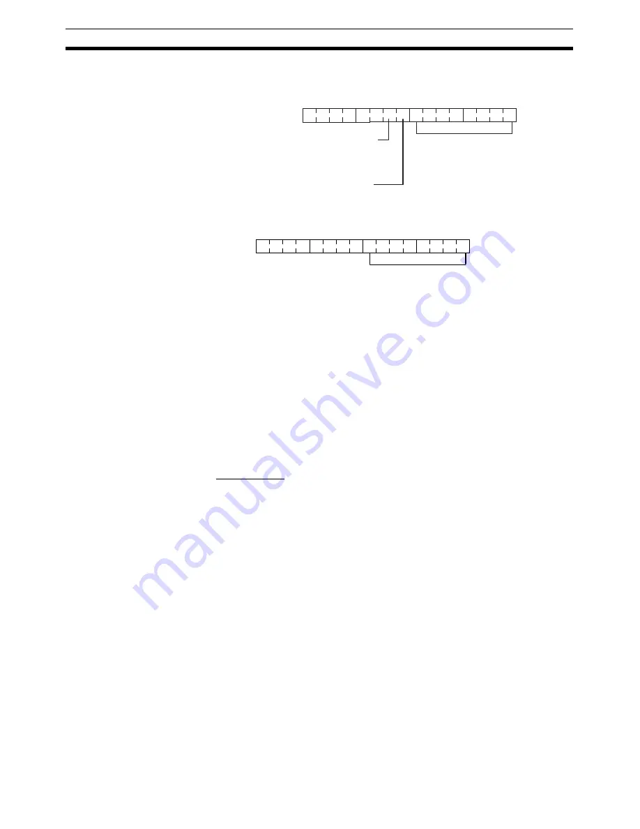
The input word (m+1) contains the 8 bits of data from the Master Unit and two
CompoBus/S communications flags.
Write the data to be transmitted to the Master Unit in the output word (n+1).
Note
(1) The 8 bits of I/O data are not always transmitted simultaneously. In other
words, 8 bits of data transmitted from the Master CPU Unit at the same
time will not always reach the Slave CPU Unit simultaneously, and 8 bits
of data transmitted from the Slave CPU Unit at the same time will not al-
ways reach the Master CPU Unit simultaneously.
When the 8 bits of input data must be read together, modify the ladder
program in the CPU Unit receiving the data. For example, read the input
data twice in succession and accept the data only when the two values
match.
(2) Unused bits in the CompoBus/S I/O Link Unit’s output word can be used
as work bits, but unused bits in the output slaves cannot be used as work
bits.
(3) Unused bits in input word cannot be used as work bits.
Determining the Node
Number and Making DIP
Switch Settings
Node Number
• The CompoBus/S I/O Link Unit is a Slave Unit with 8 input bits and 8 out-
put bits. The node number setting is made using the DIP switch; the
inputs and outputs share the same node number.
• The range of possible node number settings is determined by the type of
PC the Master Unit is mounted to and the settings on the Master Unit. For
details refer to the CompoBus/S Operation Manual.
Word m+1
15
00
07
08
09
CompoBus/S Communications Error Flag
0: Normal; 1: Error
CompoBus/S Communication Status Flag
0: Stopped; 1: Communicating
Data from the Master Unit
Word n+1
15
00
07
Data to be transferred to the Master Unit
Summary of Contents for CP1H-CPU - 05-2006
Page 2: ...CP1H X40D CP1H XA40D CP1H Y20DT D CP1H CPU Unit Operation Manual Revised May 2006...
Page 3: ...iv...
Page 11: ...xii TABLE OF CONTENTS...
Page 15: ...xvi...
Page 19: ...xx...
Page 31: ...xxxii Conformance to EC Directives 6...
Page 71: ...40 Function Blocks Section 1 5...
Page 133: ...102 Computing the Cycle Time Section 2 7...
Page 169: ...138 CPM1A Expansion I O Unit Wiring Section 3 6...
Page 411: ...380 Clock Section 6 8...
Page 519: ...488 Replacing User serviceable Parts Section 10 2...
Page 527: ...496 Standard Models Appendix A...
Page 535: ...504 Dimensions Diagrams Appendix B...
Page 628: ...597 Connections to Serial Communications Option Boards Appendix F Connecting to Unit...
Page 629: ...598 Connections to Serial Communications Option Boards Appendix F...
Page 659: ...628 PLC Setup Appendix G...
Page 665: ...634 Index work words 159 write protection 370...
Page 667: ...636 Revision History...


