411
Analog I/O Units
Section 7-4
(2)
Expansion I/O Connecting Cable
Connected to the expansion connector of a CP1H CPU Unit or a CMP1A
Expansion Unit or Expansion I/O Unit. The cable is provided with the
Analog I/O Unit and cannot be removed.
!Caution
Do not touch the cables during operation. Static electricity may cause operat-
ing errors.
(3)
Expansion Connector
Used for connecting CPM1A Expansion Units or Expansion I/O Units.
(4)
DIP Switch
Used to enable or disable averaging.
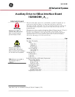
Main Analog I/O Unit
Specifications
Analog I/O Units are connected to the CP1H CPU Unit. Up to seven Units can
be connected, including any other Expansion Units and Expansion I/O Units
that are also connected.
Pin1: Average processing for analog input 0
(OFF: Average processing not performed; ON: Average processing performed)
Pin2: Average processing for analog input 1
(OFF: Average processing not performed; ON: Average processing performed)
CP1H CPU Unit
IN
00
C H
C H
02
04
06
08
10
OUT
01
C OM
03
05
07
09
11
C OM
CO M
C OM
03
CO M
06
00
01
02
04
05
07
00 01 02 03 04 05 06 07
08 09 10 11
20EDR1
C H
00 01 02 03 04 05 06 07
N C
N C
N C
C H
E X P
IN
00
02
01
C OM
03
C OM
05
07
04
06
C H 00 01 02 03
08 09 10 11
8ED
E X P
NC
NC
Possible to connect to a maximum of
7 Units including Expansion I/O Units
CPM1A-20EDR1
Expansion I/O Unit
CPM1A-8ED
Expansion I/O Unit
CPM1A-MAD11
Analog I/O Unit
1 analog output
2 analog inputs
Summary of Contents for CP1H-CPU - 05-2006
Page 2: ...CP1H X40D CP1H XA40D CP1H Y20DT D CP1H CPU Unit Operation Manual Revised May 2006...
Page 3: ...iv...
Page 11: ...xii TABLE OF CONTENTS...
Page 15: ...xvi...
Page 19: ...xx...
Page 31: ...xxxii Conformance to EC Directives 6...
Page 71: ...40 Function Blocks Section 1 5...
Page 133: ...102 Computing the Cycle Time Section 2 7...
Page 169: ...138 CPM1A Expansion I O Unit Wiring Section 3 6...
Page 411: ...380 Clock Section 6 8...
Page 519: ...488 Replacing User serviceable Parts Section 10 2...
Page 527: ...496 Standard Models Appendix A...
Page 535: ...504 Dimensions Diagrams Appendix B...
Page 628: ...597 Connections to Serial Communications Option Boards Appendix F Connecting to Unit...
Page 629: ...598 Connections to Serial Communications Option Boards Appendix F...
Page 659: ...628 PLC Setup Appendix G...
Page 665: ...634 Index work words 159 write protection 370...
Page 667: ...636 Revision History...