485
SELECTION
S
E
LECTION
3
3) Performing pre-excitation (LX signal and X13
signal) under torque control may start the motor
running at a low speed even when the start signal
(STF or STR) is not input. The motor may run also
at a low speed when the speed limit value = 0 with
a start command input. Perform pre-excitation
after making sure that there will be no problem in
safety if the motor runs.
4) Do not switch between the forward rotation
command (STF) and reverse rotation command
(STR) during operation under torque control.
Overcurrent trip (E.OC1 to 3) or opposite rotation
deceleration fault (E.11) occurs.
5) For the 0.4K to 3.7K, the speed deviation may
become large at 20Hz or less and torque may
become insufficient in the low speed range under
11Hz during continuous operation under Real
sensorless vector control. In this case, stop once
and accelerate again to improve.
6) When the inverter is likely to start during motor
coasting under Real sensorless vector control, set
to make frequency search of automatic restart
after instantaneous power failure valid [
Pr. 57
≠
9999, Pr. 162 = 10
].
7) The motor capacity should be equal to or one rank
lower than the inverter capacity. (note that the
capacity should be 0.4kW or more)
8) Single-motor operation (one motor run by one
inverter) should be performed.
(9) For selection of the vector control
For a load which requires control characteristics
equal to those of DC machines and torque control, fit
an optional FR-A7AP or FR-A7AL and select vector
control.
Vector control may be used under the following
restriction, conditions.
1) Even when motors (other manufacturer's motor,
SF-JRC, etc.) other than Mitsubishi standard
motor, high efficiency motor (SF-JR, SF-HR0.4kW
or more), Mitsubishi constant torque motor (SF-
JRCA, SF-HRCA 4-pole 0.4kW to 55kW), vector
control dedicated motor (SF-V5RU) are used,
using the offline auto tuning function runs the
motor with the optimum operating characteristics.
2) The motor capacity should be equal to or one rank
lower than the inverter capacity when using a
standard motor. (note that the capacity should be
0.4kW or more)
3) For vector control operation, the encoder should
be coupled on the same axis with the motor shaft
without any mechanical looseness. The speed
ratio should be 1:1.
4) Single-motor operation (one motor run by one
inverter) should be performed.
5) The wiring length from inverter to motor should be
within 30m.
(Perform offline auto tuning in the state where
wiring work is performed when the wiring length
exceeds 30m.)
6) For the vector control dedicated motor, the
inverter one or two ranks higher than the motor in
capacity needs to be selected depending on the
motor capacity.
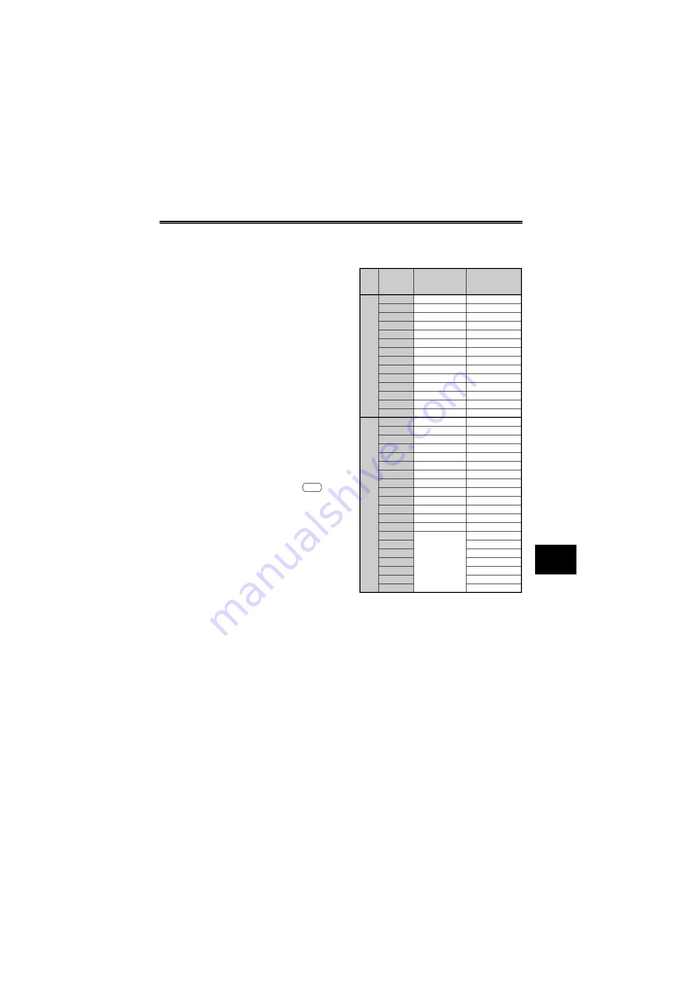
The table on the right indicates the combinations
of the SF-V5RU, SF-THY and inverter capacity.
A700
Vo
lt
a
g
e
Motor
Capacity
Motor Type
Inverter Type
200V
class
1.5kW
SF-V5RU1K
FR-A720-2.2K
2.2kW
SF-V5RU2K
FR-A720-3.7K
3.7kW
SF-V5RU3K
FR-A720-5.5K
5.5kW
SF-V5RU5K
FR-A720-7.5K
7.5kW
SF-V5RU7K
FR-A720-11K
11kW
SF-V5RU11K
FR-A720-15K
15kW
SF-V5RU15K
FR-A720-18.5K
18.5kW
SF-V5RU18K
FR-A720-22K
22kW
SF-V5RU22K
FR-A720-30K
30kW
SF-V5RU30K
FR-A720-37K
37kW
SF-V5RU37K
FR-A720-45K
45kW
SF-V5RU45K
FR-A720-55K
55kW
SF-V5RU55K
FR-A720-75K
75kW
SF-THY
FR-A720-90K
400V
class
1.5kW
SF-V5RUH1K
FR-A740-2.2K
2.2kW
SF-V5RUH2K
FR-A740-2.2K
3.7kW
SF-V5RUH3K
FR-A740-3.7K
5.5kW
SF-V5RUH5K
FR-A740-7.5K
7.5kW
SF-V5RUH7K
FR-A740-11K
11kW
SF-V5RUH11K
FR-A740-15K
15kW
SF-V5RUH15K
FR-A740-18.5K
18.5kW
SF-V5RUH18K
FR-A740-22K
22kW
SF-V5RUH22K
FR-A740-30K
30kW
SF-V5RUH30K
FR-A740-37K
37kW
SF-V5RUH37K
FR-A740-45K
45kW
SF-V5RUH45K
FR-A740-55K
55kW
SF-V5RUH55K
FR-A740-75K
75kW
SF-THY
FR-A740-90K
90kW
FR-A740-110K
110kW
FR-A740-132K
132kW
FR-A740-160K
160kW
FR-A740-185K
200kW
FR-A740-220K
250kW
FR-A740-280K
Summary of Contents for FR-A700 Series
Page 245: ...279 2 PARAMETER PARAMETER MEMO ...
Page 440: ...474 PARAMETER MEMO ...
Page 522: ...556 SELECTION MEMO ...


