339
PARAMETER
2
P
ARAM
ETE
R
*1
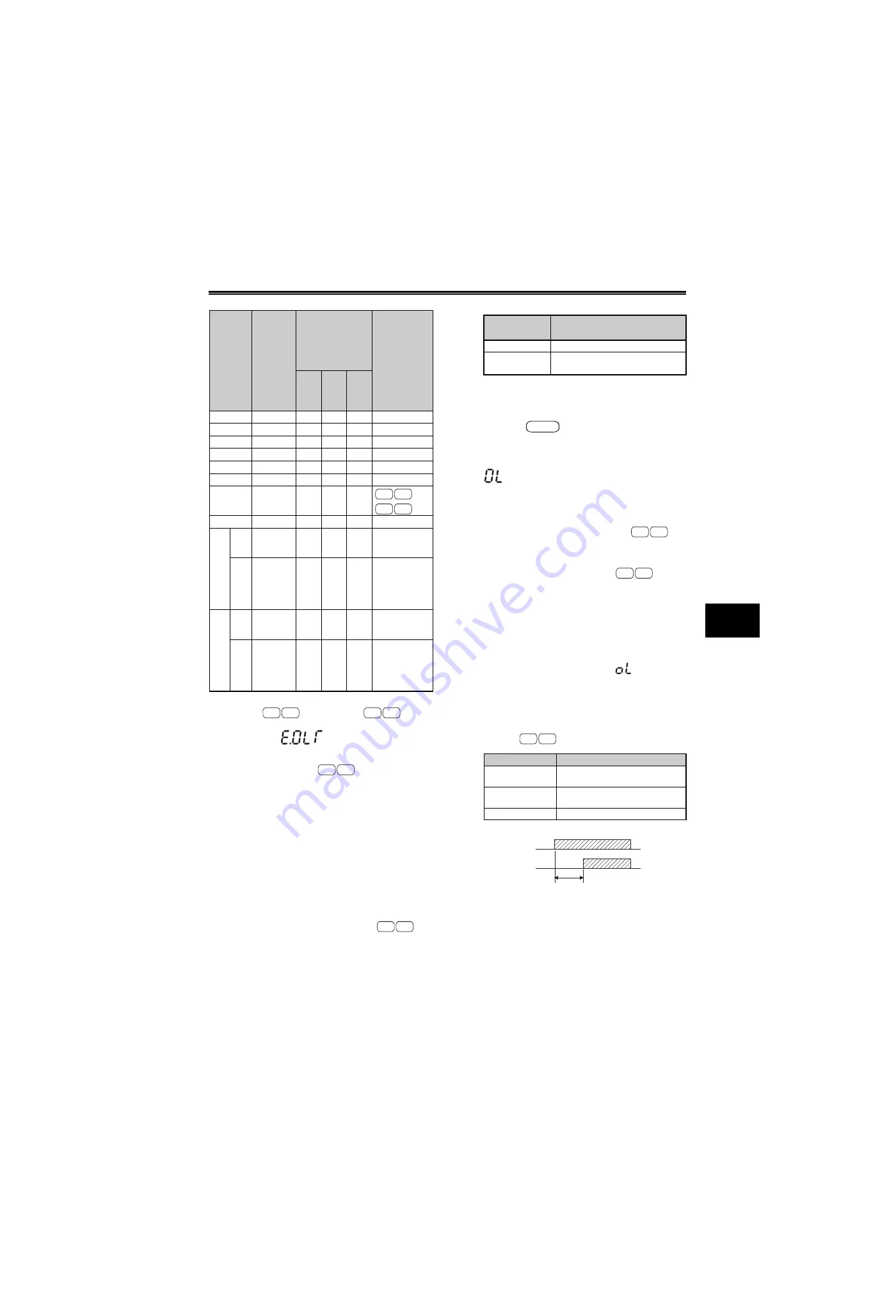
During fast-response current limit operation, OL signal is
output in
but not output in
.
*2
When "Operation not continued at OL signal output" is
selected, the "
" (stopped by stall prevention)
is displayed at OL operation and inverter trips.
*3
Stall prevention does not operate during fast-response
current limit operation in
, so the OL signal and
E.OLT are not output. However, OL signal and E.OLT are
output when regeneration avoidance function (refer to
page 340) is active.
*4
Since both fast-response current limit and stall
prevention are not activated, OL signal and E.OLT are
not output. However, OL signal and E.OLT are output
when regeneration avoidance function (refer to page
340) is active.
*5
The settings "100" and "101" allow operations to be
performed in the driving and regeneration modes,
respectively. The setting "101" disables the fast-response
current limit in the driving mode.
(6) Output voltage reduction during stall
prevention operation [Pr. 154]
When [
Pr. 154
= 0], the output voltage decreases
during stall prevention operation. By making setting
to reduce the output voltage, an overcurrent trip can
further become difficult to occur.
Use this function where a torque decrease will not
pose a problem.
(7) Stall prevention operation signal output
and output timing adjustment (OL signal)
[Pr. 157]
When the output current exceeds the stall prevention
operation level and stall prevention is activated,
(overcurrent stall) is displayed and the stall
prevention operation signal (OL signal) is ON for
longer than 100ms. When the output current falls to
or below the stall prevention operation level, the
output signal turns OFF. When using
, OL
signal is output during fast-response current limit
operation. (OL signal is not output during fast-
response current limit operation in
.)
Use [
Pr. 157 OL signal output timer
] to set whether the
OL signal is output immediately or output if stall
prevention is continuously activated after the preset
time.
This operation is also performed when the
overvoltage stall prevention operation and
regeneration avoidance function
(overvoltage
stall) are performed.
If the frequency has fallen to 0.5Hz* by stall
prevention operation and remains for 3s, a fault
(E.OLT) appears and trips the inverter.
* 1Hz for
.
24
{
{
{
z
z
25
z
{
{
z
z
26
{
z
{
z
z
27
z
z
{
z
z
28
{
{
z
z
z
29
z
{
z
z
z
30
{
z
z
z
z
—
*3
31
z
z
z
z
—
*4
100
*5
Po
w
e
r
dr
iv
ing
{
{
{
{
{
Reg
enerat
ion
z
z
z
z
—
*4
101
*5
Pow
e
r
driv
ing
z
{
{
{
{
Regener
a
tion
z
z
z
z
—
*4
[Pr. 156]
Setting
Fast
Response
Current
Limit
*1
{
: Activated
z
: Not activated
Stall Prevention
Operation
Selection
{
: Activated
z
: Not activated
OL Signal
Output
{
: Operation Continued
z
: Operation is not
Continued
*2
Ac
ce
le
ra
tio
n
Cons
ta
nt
sp
ee
d
De
ce
le
ra
tio
n
A700 F700
E700 D700
A700 F700
E700 D700
E700 D700
A700 F700
[Pr. 154]
Setting
Description
0
Output voltage reduced
1
(initial value)
Output voltage not reduced
[Pr. 157] Setting
Description
0
(initial value)
Output immediately.
0.1 to 25
Output after the set time (s) has
elapsed.
9999
Not output.
common
A700 F700
E700 D700
E700 D700
Overload state
(OL operation
㧕
OL output signal
[
Pr.157
] set time (s)
Summary of Contents for FR-A700 Series
Page 245: ...279 2 PARAMETER PARAMETER MEMO ...
Page 440: ...474 PARAMETER MEMO ...
Page 522: ...556 SELECTION MEMO ...


