218
PARAMETER
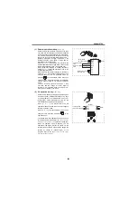
The terminal 1 (frequency setting auxiliary input)
signal is added to the main speed setting signal of
the terminal 2 or 4.
When an override is selected, the terminal 1 or 4 is
used for the main speed setting and the terminal 2 for
the override signal (50% to 150% at 0 to 5V or 0 to
10V). (When the main speed of the terminal 1 or
terminal 4 is not input, compensation by the terminal
2 is invalid.)
Use [
Pr. 125
(
Pr. 126
)
frequency setting gain
] to change
the maximum output frequency at input of the
maximum output frequency command voltage
(current).
At this time, the command voltage (current) need not
be input.
Also, the acceleration/deceleration time, which is a
slope up/down to the acceleration/deceleration
reference speed, is not affected by the change in [
Pr.
73
] setting.
When "4" is set in [
Pr. 858 Terminal 4 function
assignment
], [
Pr. 868 Terminal 1 function assignment
], the
setting of terminal 1, terminal 4 is used for stall
prevention operation level setting. When terminal 1
and terminal 4 are used for frequency setting, set "0"
(initial value) in [
Pr. 858
] and [
Pr. 868
].
Also when using
with FR-A7AZ, terminal 6 is
available. To use terminal 6 for frequency setting, set
[
Pr. 406
= 0]. (Refer to page 43)
(
indicates the main speed setting)
A700
[
Pr. 73
]
setting
Terminal 2 input
Terminal 1
input
Terminal 4 input
[
Pr. 73
]
Setting
Value
Compensation
input terminal
and
compensation
method
Polarity
reversible
Switch 2
0
OFF
0 to 10V
0 to 10V
When the AU signal is OFF
0
Terminal 1
Additional
compensation
No
(Indicates that a
frequency command
signal of negative
polarity is not
accepted.
)
1
(initial value)
OFF
0 to 5V
0 to 10V
1
(initial value)
2
OFF
0 to 10V
0 to 5V
2
3
OFF
0 to 5V
0 to 5V
3
4
OFF
0 to 10V
0 to 10V
4
Terminal 2
Override
5
OFF
0 to 5V
0 to 5V
5
6
ON
4 to 20mA
0 to 10V
6
Terminal 1
Additional
compensation
7
ON
4 to 20mA
0 to 5V
7
10
OFF
0 to 10V
0 to 10V
10
Yes
11
OFF
0 to 5V
0 to 10V
11
12
OFF
0 to 10V
0 to 5V
12
13
OFF
0 to 5V
0 to 5V
13
14
OFF
0 to 10V
0 to 10V
14
Terminal 2
Override
15
OFF
0 to 5V
0 to 5V
15
16
ON
4 to 20mA
0 to 10V
16
Terminal 1
Additional
compensation
17
ON
4 to 20mA
0 to 5V
17
0
0 to 10V
When the AU signal is ON
0
Terminal 1
Additional
compensation
No
(Indicates that a
frequency command
signal of negative
polarity is not
accepted.)
1
(initial
value)
0 to 10V
1
(initial
value)
2
0 to 5V
2
3
0 to 5V
3
4
OFF
0 to 10V
4
Terminal 2
Override
5
OFF
0 to 5V
5
6
0 to 10V
6
Terminal 1
Additional
compensation
7
0 to 5V
7
10
0 to 10V
10
Yes
11
0 to 10V
11
12
0 to 5V
12
13
0 to 5V
13
14
OFF
0 to 10V
14
Terminal 2
Override
15
OFF
0 to 5V
15
16
0 to 10V
16
Terminal 1
Additional
compensation
17
0 to 5V
17
Input
Specific-
ation
[
Pr. 267
]
setting
Switch 1
4 to
20mA
0
(Initial
value)
ON
(Initial
status)
0 to 5V
1
OFF
0 to 10V
2
OFF
Summary of Contents for FR-A700 Series
Page 245: ...279 2 PARAMETER PARAMETER MEMO ...
Page 440: ...474 PARAMETER MEMO ...
Page 522: ...556 SELECTION MEMO ...


