537
SELECTION
S
E
LECTION
3
(2) External high-duty brake resistor (FR-ABR
type)
1) Installation position
(a) When the
7.5K or less is operated in
excess of the duty of the built-in brake
resistor, disconnect the built-in brake resistor
supplied with the inverter and install an
external brake resistor.
For the
22K or less and
0.4K or more, an external brake
resistor can be installed.
(b) Since the external brake resistor generates
much heat, its surface temperature may
exceed 360 in an operation pattern using
the resistor at high-duty. Hence, install the
external brake resistor in consideration of heat
dissipation. The inverter and other devices
must not be placed above the resistor.
2) Wiring
(a) When wiring the brake resistor, note high DC
voltage application and resistor-generated
heat.
(b) The wiring distance between the inverter and
brake resistor should be as short as possible.
If it exceeds 2m, twist the cables. (If twisted,
the distance must not exceed 5m)
(c) When wiring the brake resistor, the resistor-
generated heat (maximum surface
temperature is approximately 360 ) must be
taken into consideration.
• Take measures to prevent the cables
from making contact with the resistor.
• Use heat-resistant cables (such as
glass-braided cables), or cover the
cables with silicone tubes. Use cables
of 2mm
2
or larger size.
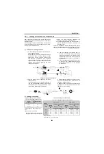
(d) The following sequence is recommended to
prevent overheat and burnout of the brake
resistor in case the brake transistor is
damaged.
Removing jumpers disables the built-in brake
resistor (power is not supplied). Note that the
built-in brake resistor is not need to be
removed from the inverter. The lead wire of
the built-in brake resistor is not need to be
removed from the terminal.
*1
Remove the jumper connected across terminal PR-PX of
the inverter. Since the
series 11K or more,
series inverter is not provided with the
PX terminal, a jumper is not need to be removed.
*2
Refer to the table below for the type number of each
capacity of thermal relay and the diagram below for the
connection. (Always install a thermal relay when using a
brake resistor whose capacity is 11K or more.)
A700
A700
E700
D700
External brake
resistor
Heat resistant
cables
Cooling fan
Install a cover
which ensures proper
heat dissipation
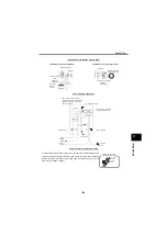
Example of installing an external brake
resistor on top of the enclosure
P
PX
PR
Inverter
*
P
PX
PR
Disconnect
a jumper
Twist
Within 5m
Brake
resistor
Brake
resistor
Inverter
Within 2m
*
Disconnect
a jumper
Wiring the brake resistor
* Since the
series 11K or more,
series inverter is not provided with the PX terminal, a
jumper is not need to be removed.
A700
E700
D700
Power
Supply
Voltage
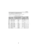
High-duty
Brake Resistor
Thermal Relay Type
(Mitsubishi Product)
Contact Rating
200V
FR-ABR-0.4K
TH-N20CXHZ-0.7A
110VAC 5A,
220VAC 2A
(class 11AC )
110VDC 0.5A,
220VDC 0.25A
(class 11DC)
FR-ABR-0.75K
TH-N20CXHZ-1.3A
FR-ABR-2.2K
TH-N20CXHZ-2.1A
FR-ABR-3.7K
TH-N20CXHZ-3.6A
FR-ABR-5.5K
TH-N20CXHZ-5A
FR-ABR-7.5K
TH-N20CXHZ-6.6A
FR-ABR-11K
TH-N20CXHZ-11A
FR-ABR-15K
TH-N20CXHZ-11A
FR-ABR-22K
TH-N60-22A
400V
FR-ABR-H0.4K
TH-N20CXHZ-0.24A
FR-ABR-H0.75K TH-N20CXHZ-0.35A
FR-ABR-H1.5K
TH-N20CXHZ-0.9A
FR-ABR-H2.2K
TH-N20CXHZ-1.3A
FR-ABR-H3.7K
TH-N20CXHZ-2.1A
FR-ABR-H5.5K
TH-N20CXHZ-2.5A
FR-ABR-H7.5K
TH-N20CXHZ-3.6A
FR-ABR-H11K
TH-N20CXHZ-6.6A
FR-ABR-H15K
TH-N20CXHZ-6.6A
FR-ABR-H22K
TH-N20-9A
MC
MC
R
PX
PR
P/+
S/L2
T/L3
R/L1
ON
OFF
F
M
C
High-duty
brake resistor
(FR-ABR)
Thermal
relay
(OCR)(*2)
Inverter
Disconnect jumper. (*1)
Power
Supply
<Example 1>
OCR
Contact
MC
MC
T
R
PX
PR
P/+
S/L2
T/L3
R/L1
ON
OFF
B
C
F
M
C
Power
Supply
<Example 2>
Inverter
(OCR)(*2)
Thermal
relay
(FR-ABR)
High-duty
brake resistor
Disconnect jumper. (*1)
OCR
Contact
A700
E700
D700
To the inverter
P/+ terminal
To the ABR
TH-N20
1/L
1
5/L
3
2/T
1
6/T
3
Summary of Contents for FR-A700 Series
Page 245: ...279 2 PARAMETER PARAMETER MEMO ...
Page 440: ...474 PARAMETER MEMO ...
Page 522: ...556 SELECTION MEMO ...


