33
1
S
PECIFI
C
A
T
IONS
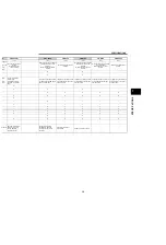
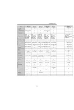
SPECIFICATIONS
*1
Terminal function can be changed using [
Pr. 178 to Pr. 189 Input terminal assignment
].
*2
Terminal function can be changed using [
Pr. 190 to Pr. 196 Output terminal assignment
].
*3
The description at a fault occurrence can be output by 4 bit digital signal using [
Pr. 76 Fault code output selection
].
*4
Low indicates that the open collector output transistor is ON (conducts).
High indicates that the transistor is OFF (does not conduct).
*5
Monitor to be output to terminal FM can be changed using [
Pr. 54 FM terminal function selection
].
*6
Monitor to be output to terminal AM can be changed using [
Pr. 158 AM terminal function selection
].
US
B
—
USB
connector
Interface : conforms to USB1.1
Transmission speed : 12Mbps
Connector :
USB B connector
(B receptacle)
USB mini B connector
(mini B receptacle)
FR Configurator can be operated by
connecting the inverter to the
personal computer through USB.
{
—
{
—
Sa
fe
ty
fu
n
cti
o
n
S1
Inverter
output
shutoff
(Line 1)
—
Inverter output is shutoff depending
on shorting/opening between S1 and
SC, or between S2 and SC. At initial
state, terminal S1 and S2 are shorted
to terminal SC with a shorting wire.
When using the safety stop function,
remove this shorting wire, and
connect to a safety relay module.
—
—
—
{
S2
Inverter
output
shutoff
(Line 2)
—
—
—
{
SO
Safety
monitor
output
(open
collector
output)
Switched low when inverter output is
shutoff by safety stop function, and
high during other state.
*4
—
—
—
{
SC
Output
shutoff
terminal
common
Common terminal for terminals S1,
S2 and SO. Connected to terminal
SD inside of the inverter.
—
—
—
{
Ty
p
e Terminal
Symbol
Terminal
Name
Rating, etc.
Application Explanation
Available Inverters
Refer
to
Page
A700
F700
E700
D700
A700
E700
Summary of Contents for FR-A700 Series
Page 245: ...279 2 PARAMETER PARAMETER MEMO ...
Page 440: ...474 PARAMETER MEMO ...
Page 522: ...556 SELECTION MEMO ...


