263
2
P
ARAM
ETE
R
PARAMETER
2.7.6
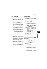
Vector control [Pr. 71, 80, 81, 359, 369, 800]
(A700)
This method divides the currents flowing in the motor into a
current for making a magnetic flux in the motor and a
current for causing the motor to develop a torque and
controls each current separately. Therefore, very high
response is obtained and torque at low speed can be
generated stably.
It is necessary to know the motor speed to perform this
control, and a motor with an encoder and a plug-in option
FR-A7AP or FR-A7AL are required.
It responds to the load variation quickly (high response) by
torque current control, and torque control is also enabled
by giving torque command.
It has excellent control characteristics and achieves the
control characteristics equal to those of DC machines.
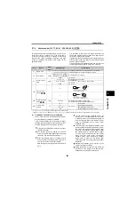
(1) Conditions of vector control selection
Vector control may only be utilized effectively when
all of the following conditions are satisfied.
If any of the conditions cannot be satisfied, torque
shortage, speed fluctuation or another fault may have
occurred. Operate under V/F control in that case.
A700
[
Pr.
]
Name
Initial
Value
Setting Range
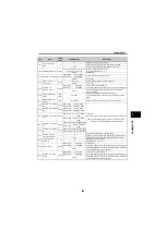
Description
71
Applied motor
0
0 to 8, 13 to 18, 20, 23, 24, 30,
33, 34, 40, 43, 44, 50, 53, 54
By selecting a standard motor or constant torque motor, thermal
characteristic and motor constants of each motor are set.
80
Motor capacity
9999
55K or less
0.4 to 55kW
Set the applied motor capacity.
75K or more
0 to 3600kW
9999
V/F control
81
Number of motor
poles
9999
2, 4, 6, 8, 10
Set the number of motor poles.
12, 14, 16, 18, 20
X18 signal-ON:
V/F control *
Set 10 + number of motor poles .
9999
V/F control
359
Encoder rotation
direction
1
0
1
369
Number of encoder
pulses
1024
0 to 4096
Set the number of pulses of the encoder.
Set the number of pulses before multiplied by four.
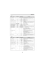
800
Control method
selection
20
0 to 5
V/F control **
Vector control
9
Vector control test operation
10, 11, 12
Real sensorless vector control
20
Advanced magnetic flux vector control
* Use [
Pr. 178 to Pr. 189
] to assign the terminals used for the X18 and MC signal.
** When [
Pr. 80 Motor capacity
= 9999] or [
Pr. 81 Number of motor poles
= 9999], control method is V/F control regardless of the [
Pr. 800
] setting.
A
Encoder
CW
Clockwise direction as viewed
from A is forward rotation
CCW
A
Encoder
Counter clockwise direction as
viewed from A is forward rotation
A plug-in option FR-A7AP or FR-A7AL should be
fitted to the inverter.
The encoder should be coupled on the same
axis with the motor shaft without any mechanical
looseness. The speed ratio should be 1:1.
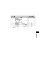
When the standard motor or constant motor is
used, the motor capacity should be equal to or
one rank lower than the inverter capacity.
Note that the motor capacity should be 0.4kW or
more.
For the vector control dedicated motor, the
inverter one or two ranks higher than the motor
in capacity needs to be selected depending on
the motor capacity. Refer to the table on the next
page for combination with a vector control
dedicated motor.
The motor type is the Mitsubishi standard motor
with an encoder, Mitsubishi high efficiency motor
(SF-JR, SF-HR 2 poles, 4 poles, 6 poles 0.4kW
or more) or Mitsubishi constant torque motor
(SF-JRCA 4 poles, SF-HRCA 0.4kW to 55kW),
or vector control dedicated motor (SF-V5RU).
When any other motor (other manufacturer
standard motor, other manufacturer constant
torque motor) is used, use this function after
performing offline auto tuning (refer to page268)
without fail .
Single-motor operation (one motor run by one
inverter) should be performed.
Wiring length from inverter to motor should be
within 30m. If the length is over 30m, perform
offline auto tuning with the cables wired.
Summary of Contents for FR-A700 Series
Page 245: ...279 2 PARAMETER PARAMETER MEMO ...
Page 440: ...474 PARAMETER MEMO ...
Page 522: ...556 SELECTION MEMO ...


