561
4
P
RACTICAL CIRC
UI
T
S
PRACTICAL CIRCUITS
4.1.4
The inverter without magnetic contactor on the primary side
(common)
*1
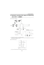
Set [
Pr. 75
= 1] "Reset input is enabled only when the fault occurs" to disable resetting of the inverter during normal operation. (If
the inverter is reset during normal operation, the motor coasts to a stop. This setting is to prevent the inverter from resulting in
an alarm if the motor is still coasting when the inverter has returned from the reset status.)
*2
During operation, switch-over from "forward rotation" to "stop", then to "reverse rotation" is available.
In this case, when the reverse rotation signal is turned ON, the regenerative brake is applied down to the forward rotation
frequency of 0.5Hz, the opposite-phase brake is applied at or less than starting frequency and acceleration in reverse rotation is
started at that frequency. (DC injection brake is not applied.)
*3
When making "forward rotation" to "reverse rotation" change-over during forward rotation in the above chart, change part of the
connection diagram as shown on the above.
*4
When an inverter with a regenerative brake resistor is used for cyclic or heavy duty operation, it is recommended to install a
magnetic contactor in the primary side to prevent the discharging resistor from overheat/burnout if the regenerative brake
transistor is damaged due to the thermal capacity shortage of the discharging resistor, and excessive regenerative brake duty,
etc.
*5
When the power supply is 400V class, install a step-down transformer.
common
IM
U
V
W
R
S
T
B
C
RES
SD
STF
STR
FM
10
2
5
MCCB
T
*5
F
PB3
R
F
R
F
F
R
*1
F
R
Hz
(1)
(2)
(3)
Power
supply
Frequency setting
potentiometer
2W1k
Inverter
Motor
Ground
Related parameter
Reset selection, Pr. 75
Frequency meter
Moving-coil type 1mA
PB (Reset)
Reverse rotation
PB2
Stop
Forward rotation
PB1
PB3
F
F
R
PB1
PB2
R
F
R
Speed
Change-over from forward
rotation to reverse rotation
Time
Acceleration
Reverse rotation
Opposite-phase brake
Stop
Forward
rotation
Reverse
rotation
Forward
rotation
Deceleration
Summary of Contents for FR-A700 Series
Page 245: ...279 2 PARAMETER PARAMETER MEMO ...
Page 440: ...474 PARAMETER MEMO ...
Page 522: ...556 SELECTION MEMO ...


