519
SELECTION
S
E
LECTION
3
(2) Radio EMI
When the motor is driven from the inverter, high
frequency EMI is radiated to the air from the inverter.
Like radio-wave EMI, this EMI has a great influence
on the frequency band of less than 10MHz and may
generate noise when entering into a radio receiver.
The radio EMI suppressing methods, radio EMI
propagation paths and measurement methods are
given below.
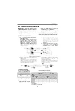
1) EMI propagation paths
Major propagation paths of the radio-wave EMI
from the source of noise to a receiver affected
may be as indicated below:
2) EMI measuring methods
(a) Measurement of EMI terminal voltage
Disturbance wave strength flowing into the
power cord of the disturbing device is
measured as a disturbance wave voltage on
the distribution line where that device is
connected.
The measured value is indicated on dB (1 V
= 0dB).
(b) Measurement of EMI field strength
The strength of the electric field radiated by
the disturbing device to the air is measured
with an antenna. The distance of
measurement between the devices and
antenna is specified as 10m or 3m. The
measured value is indicated on dB (1 V/m =
0dB).
(c) Also, disturbing power or the discontinuous
EMI (click EMI) of a contact device is
measured depending on the EMI type.
As described above, the evaluation of
disturbance wave EMI depends greatly on the
difference of its propagation path and the type
of EMI measuring method. The most
appropriate method for comparing actual
harm to the radio receiver by the disturbance
wave is to measure the propagation EMI field
strength because the receiver is mostly
influenced by the propagation paths (a), (c) or
(d).
3) Countermeasures against radio EMI
Radio EMI can be reduced by any of the following
methods:
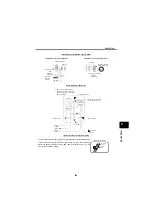
(a) Connect the capacitor type filter (FR-BIF)
dedicated to FR-series inverters across the
inverter input power supply terminals (Phase
R, S, T) and securely ground it with the
ground cable. This is effective when the wiring
distance between the inverter and motor is
short.
are equipped with a built-in noise
filter that is equivalent to a capacitor noise
filter. Using the ON/OFF connector, whether to
connect to the earth (ground) or not can be
selected. (ON/OFF connector is not available
for FR-A720-0.4K, 0.75K, and 1.5K.
Connector is always in ON status.)
(b) When the wiring distance between the inverter
and motor is long, run the cable between the
inverter and motor in a grounding conduit.
(a) Direct radiation
EMI radiated directly from the EMI source
as an airborne wave and entering the
antenna and circuit of the receiver.
(b) Direct transmission
EMI of which current is transmitted through
the power supply line and enters the
receiver.
(c) Radiation from the power supply line
EMI which leaks to the power supply line is
radiated from the distribution line and
enters the receiver.
(d) Radiation from the power cables
EMI which is radiated from the wiring
between the inverter and motor and enters
the receiver.
IM
Motor
Inverter
Antenna
Radio
receiver
Transformer
200V power supply line
d
a
c
b
Radio EMI propagation paths
* In this case, one FR-BIF causes an approx.
4mA for the 200V (approx. 8mA for the 400V)
leakage current to flow. (equivalent to one
phase of the three-phase, three wire,
connection power supply)
Power
MCCB
Earthing
(grounding)
FR-BIF
R
S
T
Inverter
Capacitor type filter
A700
F700
Power
FR-BIF
*
A shield cable is
also effective.
Inverter
IM
*
Grounding conduit
Summary of Contents for FR-A700 Series
Page 245: ...279 2 PARAMETER PARAMETER MEMO ...
Page 440: ...474 PARAMETER MEMO ...
Page 522: ...556 SELECTION MEMO ...


