224
PARAMETER
(7) Bias and gain of frequency setting voltage
(current) [
Pr. 125, 126, 241, C2 to C7(Pr. 902 to
905), C30 to C33* (Pr. 926, 927)
]
(Available in
with FR-A7AZ.)
You can set the magnitude (slope) of the output
frequency as desired in relation to the frequency
setting signal (0 to 5VDC, 0 to 10VDC or 4 to
20mADC).
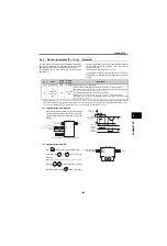
Refer to the following diagram for the relationships
between the frequency setting signal and output
frequencies. When using terminal 1 added
compensation, terminal 2 (4) analog value + terminal
1 analog value is the analog calibration value.
1) Change the frequency at maximum analog input
Set a value in [
Pr. 125 (126)
] when changing only
the frequency setting (gain) of the maximum
analog input voltage (current). [
(C2 (Pr. 902) to C7
(Pr. 905)
] setting need not be changed. Set a value
in [
C32 (Pr. 927)
] when using terminal 6 in
with FR-A7AZ.
2) Calibration of analog input bias and gain
As for voltage between frequency setting power
supply terminal 10 (10E) and terminal 5, and input
impedance of analog input terminal, there are
variability in each inverters. Therefore exact
output frequency for the frequency setting input is
different in each inverters. When using a common
frequency setting input for multiple inverters,
calibration of frequency setting bias [
C3 (C6)
] and
gain [
C4(C7)
] is required for each inverters.
When applying voltage (current) for calibration,
the difference of the frequency setting input
voltage (current) of [
C3
] and [
C4
] ([
C6
] and [
C7
])
should be 0.5V (2mA) or more. If the difference is
0.5V (2mA) or less, a setting error will occur.
Calibrate with [
C31 to C33 (Pr. 926, 927)
] when using
terminal 6 in
with FR-A7AZ.
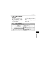
3) Analog input display unit changing
You can change the analog input display unit (%/
V/mA) for analog input bias/gain calibration.
Depending on the terminal input specification set
to [
Pr. 73
], [
Pr. 267
], the display units of [
C3(Pr.
902)
], [
C4(Pr. 903)
], [
C6(Pr. 904)
], [
C7(Pr. 905)
],
[
C31(Pr. 926)
], [
C33(Pr. 927)
] change as shown
below.
Analog input display is not displayed correctly if
voltage is applied to terminal 1 when terminal 1
input specifications (0 to 5V, 0 to 10V) and
main speed (terminal 2, terminal 4 input)
specifications (0 to 5V, 0 to 10V, 0 to 20mA) differ.
(For example, 5V (100%) is analog displayed
when 0V and 10V are applied to terminal 2 and
terminal 1 respectively in the initial status.)
In this case, set [
Pr. 241 = 0
] (% display).
common
A700
60Hz
Output frequency
(Hz)
[
Pr. 125 (903)
]
0
0
Frequency setting signal
100%
10V
Initial value
Bias
Gain
0
5V
[
C2 (Pr. 902)
]
[
C3 (Pr. 902)
]
[
C4 (Pr. 903)
]
Output frequency
(Hz)
[
Pr. 126 (905)
]
0
Frequency setting signal
100%
Initial value
Bias
Gain
0
20
4
20mA
[
C5 (Pr. 904)
]
[
C6 (Pr. 904)
]
[
C7 (Pr. 905)
]
60Hz
A700
Analog
Command
(terminal 2, 4)
[
Pr. 73, 267
]
[
Pr. 241 = 0
]
(initial value)
[
Pr. 241 = 1
]
0 to 5V input
Displayed in 0 to 100%
(0.1% increments)
Displayed in 0 to 5V
(0.01V increments)
0 to 10V input
Displayed in 0 to 100%
(0.1% increments)
Displayed in 0 to 10V
(0.01V increments)
0 to 20mA input
Displayed in 0 to 100%
(0.1% increments)
Displayed in 0 to 20mA
(0.01mA increments)
A700
[
Pr.
]
Name
Initial
Value
Setting
Range
Description
125(903) Terminal 2 frequency setting gain frequency
60Hz 0 to 400Hz Set the frequency of terminal 2 input gain (maximum).
126(905) Terminal 4 frequency setting gain frequency
60Hz 0 to 400Hz Set the frequency of terminal 4 input gain (maximum).
241
Analog input display unit switchover
0
0
Displayed in %
Selects the unit for analog input display.
1
Displayed in V/mA
C2(902) Terminal 2 frequency setting bias frequency
0Hz
0 to 400Hz Set the frequency on the bias side of terminal 2 input.
C3(902) Terminal 2 frequency setting bias
0%
0 to 300% Set the converted % of the bias side voltage (current) of terminal 2 input.
C4(903) Terminal 2 frequency setting gain
100%
0 to 300% Set the converted % of the gain side voltage of terminal 2 input.
C5(904) Terminal 4 frequency setting bias frequency
0Hz
0 to 400Hz Set the frequency on the bias side of terminal 4 input.
C6(904) Terminal 4 frequency setting bias
20%
0 to 300% Set the converted % of the bias side current (voltage) of terminal 4 input.
C7(905) Terminal 4 frequency setting gain
100%
0 to 300% Set the converted % of the gain side current (voltage) of terminal 4 input.
C30(926) Terminal 6 bias frequency (speed)
0Hz
0 to 400Hz Set the frequency on the bias side of terminal 6 input.
C31(926) Terminal 6 bias (speed)
0%
0 to 300% Set the converted % on the bias side voltage of terminal 6 input.
C32(927) Terminal 6 gain frequency (speed)
60Hz 0 to 400Hz Set the frequency on the gain side of terminal 6 input.
C33(927) Terminal 6 gain (speed)
100%
0 to 300% Set the converted % on the gain side voltage of terminal 6 input.
Summary of Contents for FR-A700 Series
Page 245: ...279 2 PARAMETER PARAMETER MEMO ...
Page 440: ...474 PARAMETER MEMO ...
Page 522: ...556 SELECTION MEMO ...


