534
SELECTION
3.6.8
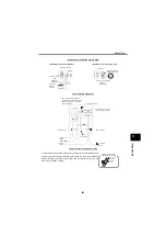
Frequency setting potentiometer
Type: WA2W 1k
Ω
Wire-wound variable resistor 2W1k
Ω
B characteristics
When frequency setting is not changed frequently, a
variable resistor of 1/2W1k
Ω
may be used.
3.6.9
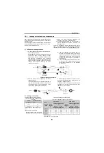
Frequency meter and calibration resistor
A manual controller with frequency meter (such as the FR-
AX) is available. When only a frequency meter is installed
separately, use an instrument of the following
specifications:
Moving-coil type DC ammeter
Full scale 1mA (internal resistance 300
Ω
max.)
Since the frequency meter terminal FM on the inverter
develops about 5VDC at the maximum frequency, calibrate
the frequency meter using the variable resistor having the
following specifications. It is not necessary when
calibrating the meter from the operation panel (parameter
unit).
Calibration resistor 1/3W or more 10k
Ω
The following frequency meter and calibration resistor are
available for use.
z
Analog frequency meter(64mm
×
60mm)
Type YM206NRI 1mA
Graduations : 0 to 65, 130Hz double graduations
z
Calibration resistor
Type: RV24YN 10k
Ω
Deposited carbon variable resistor 1/3W, 10k
Ω
B
characteristic
30
20
6
12
25
1
2
3
30
MAX
R25
12
12
2.8 (locking)
M9 0.75 screw
Panel drilling diagram
3.6 hole
10 hole
(Unit: mm)
Graduations:
60, 120, 240Hz in full scale.
Alternatively, graduate in rpm
according to the number of poles
of the motor used.
64
60
53
2-M3
0.5
10
25
43
10.5
M4 0.7 screw
Panel drilling diagram
24
24
24
24
55mm dia. hole
2-
4mm dia. hole
(Unit: mm)
30
60
20
40
10
20
0
40
80
50
100
60
120
(for terminal)
(for installation)
* Not needed when the operation panel (FR-DU07) or
parameter unit (FR-PU07) is used for calibration. This
resistor is used when calibration must be made near the
frequency meter for such a reason as a remote
frequency meter. Note that the needle of the frequency
meter may not deflect to full-scale when the calibration
resistor is connected. In this case, use this resistor and
operation panel or parameter unit together.
2.5
M9
0.75 screw
6
10
13
20
2.8
10
MAX
R22
1
2
3
Panel drilling diagram
3.6mm
dia. hole
10
(Unit: mm)
24
10mm
dia. hole
Summary of Contents for FR-A700 Series
Page 245: ...279 2 PARAMETER PARAMETER MEMO ...
Page 440: ...474 PARAMETER MEMO ...
Page 522: ...556 SELECTION MEMO ...


