


415
PARAMETER
2
P
ARAM
ETE
R
(6) Output signal
PID signal turns ON during dancer control (PID control) or at a stop by PID control (in the status PID operation being
performed inside). (The signal is OFF during normal operation.)
For the terminal used for PID signal output, assign the function by setting "47 (positive logic) or 147 (negative logic)" in any of
[
Pr. 190 to Pr. 192 (output terminal function selection)
].
(7)
PID monitor function
The PID control set point and measured value can be output to the operation panel monitor display and terminal FM.
For each monitor, set the following value in [
Pr. 52 DU/PU main display data selection
] and [
Pr. 54 FM terminal function selection
].
(8) Priorities of main speed command
The priorities of the main speed speed command
source when the speed command source is external
are as follows.
JOG
signal
>
multi-speed setting signal (RL/RM/RH/
REX)
>
16 bit digital input (option)
>
terminal
2
The priorities of the main speed speed command
source when "3" is set in [
Pr. 79
] are as follows.
Multi-speed setting signal (RL/RM/RH/REX)
>
set
frequency (digital setting by PU, operation panel)
Terminal 4 can not be selected as the main speed
speed command even when AU terminal is turned
ON.
Even when a remote operation function is selected
by setting [
Pr. 59
≠
0], compensation of the remote
setting frequency to the main speed is ignored
(changes to 0).
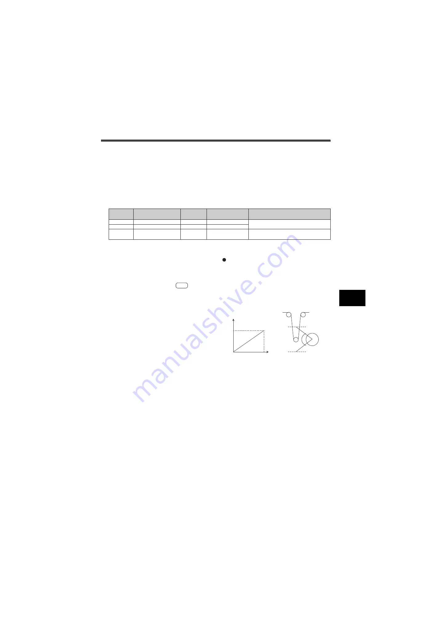
(9) Adjustment procedure
Dancer roll position detection signal
adjustment
When terminal 4 input is voltage input, 0V is the lower limit
position and 5V(10V) is the upper limit position. When
current is input, 4mA is the lower limit position and 20mA is
the upper limit position (initial value). When 0 to 7V is
output from the potentiometer, it is necessary to calibrate [
C7 (Pr .905)
]
at 7V.
(Example) Control at a dancer center position using a 0 to
7V potentiometer
1) After changing the current/voltage input switch to
"V", set "2" in [
Pr. 267
= 2] to change terminal 4
input to voltage input.
2) Input 0V to across terminal 4 and 5 to calibrate [
C6 (Pr. 904)
]. (% display displayed at analog
calibration is irrelevant to % of the feedback
value.)
3) By inputting 7V across terminal 4 to 5, calibrate [
C7(Pr. 905)
]
(% display displayed at analog
calibration is irrelevant to % of the feedback
value.)
4) Set 50% in [
Pr.133
].
Setting
Monitor Description
Minimum
Increments
Terminal FM Full
Scale
Remarks
52
PID set point
0.1%
100%
—
53
PID measured value
0.1%
100%
54
PID deviation value
0.1%
—
Value cannot be set in [
Pr. 54
].
Displays 1000 when the PID deviation is 0%.
E700
5V(10V)
0V
20mA
4mA
0%
Feedback value
Potentiometer, etc.
Lower limit
position
Upper limit
position
100%
Summary of Contents for FR-A700 Series
Page 245: ...279 2 PARAMETER PARAMETER MEMO ...
Page 440: ...474 PARAMETER MEMO ...
Page 522: ...556 SELECTION MEMO ...


