570
PRACTICAL CIRCUITS
4.5.2
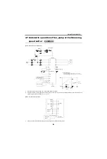
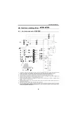
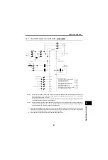
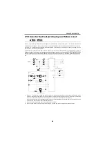
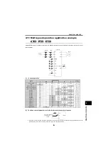
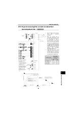
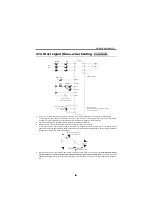
Bypass inverter switch-over operation
(common)
Bypass operation can be changed over to inverter operation without stopping the motor.
(Setting [
Pr. 57
≠
9999
]
will make the restart function valid.)
*1
For
, when coasting the motor to a stop by pressing the stop pushbutton in the inverter mode, modify the circuit
as shown below:
*2
By pressing the inverter operation pushbutton, bypass operation can be changed over to inverter operation without stopping the
motor.
*3
For
, when the inverter is tripped due to an instantaneous power failure (IPF), the motor restarts automatically
when power is restored. (Note that when there is no type RD instantaneous power failure relay, the motor is coasted to a stop
when the relay or MC turns OFF, and does not restart automatically.)
*4
When an inverter trip occurs, inverter operation is changed over to bypass operation. (When the RA1 marked *4 is removed,
bypass backup operation is not performed.)
*5
When the stop pushbutton is pressed during inverter operation, the motor is inverter-controlled from deceleration to a stop.
(When coating the motor to a stop, modify the circuit portions marked *1 and *7.)
*6
When the power supply is 400V class, install a step-down transformer.
*7
do not have CS signal. Assign MRS signal and set the MRS signal logic as normally closed ([
Pr. 17
=2]). Also,
set to perform frequency search at every power ON ([
Pr. 162
=10]) for automatic restart after instantaneous power failure.
common
IM
U
V
W
R
S
T
T
*6
F
MC
10
2
5
MC1 OCR
B
C
(2)
(3)
(1)
MI
MC2
Reset
PB
RES
SD
STF
CS
RA2
CR2
*1
*7
X
Y
Inverter
MCCB
Power
supply
Motor
Related parameters
Restart selection [
Pr. 57, 58
]
(Set [
Pr. 57 9999
])
Reset selection [
Pr. 75
]
Fault signal
Frequency setting
potentiometer
2W1k
A700
F700
SD
STF
CS
CR2
A700
F700
E700
D700
Summary of Contents for FR-A700 Series
Page 245: ...279 2 PARAMETER PARAMETER MEMO ...
Page 440: ...474 PARAMETER MEMO ...
Page 522: ...556 SELECTION MEMO ...


