


364
PARAMETER
2.15.8 Display of the life of the inverter parts [Pr. 255 to 259]
(common)
Degrees of deterioration of main circuit capacitor, control
circuit capacitor, cooling fan and inrush current limit circuit
can be diagnosed by monitor.
When any part has approached the end of its life, an alarm
can be output by self diagnosis to prevent a fault.
(Use the life check of this function as a guideline since the
life except the main circuit capacitor is calculated
theoretically.)
For the life check of the main circuit capacitor, the alarm
signal (Y90) will not be output if a measuring method of (4)
is not performed.
(1) Life alarm display and signal output (Y90 signal) [Pr. 255]
Whether any of the control circuit capacitor, main
circuit capacitor, cooling fan and inrush current limit
circuit has reached the life alarm output level or not
can be checked by [
Pr. 255 Life alarm status display
]
and life alarm signal (Y90).
The life alarm signal (Y90) turns ON when any of the
control circuit capacitor, main circuit capacitor,
cooling fan and inrush current limit circuit reaches the
life alarm output level.
For the terminal to output Y90 signal, assign 90
(positive logic) or 190 (negative logic) to any of
[
Pr.190 to 196 Output terminal function selection
],
[
Pr.190 to 192 Output terminal function selection
], or
[
Pr.190, 192 Output terminal function selection
].
When using a built-in option (FR-A7AY, FR-A7AR) in
, the following life signals can be
output individually: control circuit capacitor life signal
(Y86), main circuit capacitor life signal (Y87), cooling
fan life signal (Y88), and inrush current limit circuit life
signal (Y89).
common
[Pr. ]
Name
Initial
Value
Setting
Range
Description
255
Life alarm status display
0
(0 to 15)
Displays whether the control circuit capacitor, main circuit capacitor, cooling
fan, and each parts of the inrush current limit circuit has reached the life alarm
output level or not. Reading only
256
Inrush current limit circuit
life display
100%
(0 to 100%)
Displays the deterioration degree of the inrush current limit circuit. Reading
only
257
Control circuit capacitor
life display
100%
(0 to 100%) Displays the deterioration degree of the control circuit capacitor. Reading only
258
Main circuit capacitor life
display
100%
(0 to 100%)
Displays the deterioration degree of the main circuit capacitor. Reading only
The value measured by [
Pr. 259
] is displayed.
259
Main circuit capacitor life
measuring
0
0, 1
(2, 3, 8, 9)
Setting 1 and switching the power supply OFF starts the measurement of the main
circuit capacitor life.
Switch the power supply ON again and check the [
Pr. 259
] setting. Measurement is
complete if the setting is 3. Displays the deterioration degree in [
Pr. 258
] .
A700 F700
E700
D700
A700 F700 E700
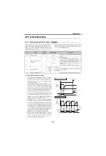
0 0 0 0 0 0 0 0 0 0 0 0 1 0 0 1
15
bit
7
0
bit0 Control circuit capacitor life
bit1 Main circuit capacitor life
bit2 Cooling fan life
bit3 Inrush current limit circuit life
•
Pr.255
read
Bit image is displayed
in decimal
•
Pr.255
setting read
[Pr. 255]
(Decimal)
Bit
(Binary)
Inrush Current
Suppression Circuit Life
Cooling Fan Life
Main Circuit
Capacitor Life
Control Circuit
Capacitor Life
15
1111
{
{
{
{
14
1110
{
{
{
×
13
1101
{
{
×
{
12
1100
{
{
×
×
11
1011
{
×
{
{
10
1010
{
×
{
×
9
1001
{
×
×
{
8
1000
{
×
×
×
7
0111
×
{
{
{
6
0110
×
{
{
×
5
0101
×
{
×
{
4
0100
×
{
×
×
3
0011
×
×
{
{
2
0010
×
×
{
×
1
0001
×
×
×
{
0
0000
×
×
×
×
{
: With warnings,
×
: Without warnings
Summary of Contents for FR-A700 Series
Page 245: ...279 2 PARAMETER PARAMETER MEMO ...
Page 440: ...474 PARAMETER MEMO ...
Page 522: ...556 SELECTION MEMO ...


