


523
SELECTION
S
E
LECTION
3
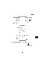
Instructions for installation of noise filters
<Installation in inverter input side>
<Installation in inverter output side>
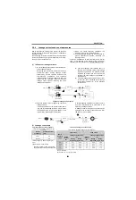
Cable routing in control box
Instructions for encoder cable wiring
R (L
1
)
S (L
2
)
T (L
3
)
FR-BIF
FR-BLF
FR-BSF01
Shortest distance
Inverter
Common mode
filter
Wire over
shortest
distance.
U
V
W
In
ve
rter
Shortest
Number of winds
within 3 times (4T).
Motor
FR-BLF
FR-BSF01
Common mode filter
U. Masking shield
S. Separate by more than
30cm (at least 10cm).
Inverter
Noise filter
Terminal block
Connection
Terminal block
Power
supply
Control
supply
T. Run cables as separately as
possible and do not run cables in
parallel or together. Cross them
where inevitable.
Microcomputer
board
Programmable
controller
Motor
Limit switch
Sensor
• To reduce EMI of the encoder cable, earth (ground) the encoder shielded cable
to the enclosure (as near as the inverter) with a P clip or U clip made of metal. To
protect the cables from EMI, run them away from any source of noise (e.g. the
main circuit and power voltage).
Encoder
cable
Shield
P clip
Earthing (grounding)
example using a P clip
Summary of Contents for FR-A700 Series
Page 245: ...279 2 PARAMETER PARAMETER MEMO ...
Page 440: ...474 PARAMETER MEMO ...
Page 522: ...556 SELECTION MEMO ...


