566
PRACTICAL CIRCUITS
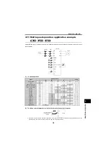
4.4.2
Inverters and motors are in pairs
(common)
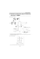
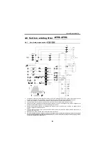
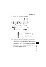
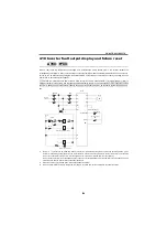
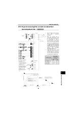
[Ratio control operation]
The ratio setting potentiometer may be omitted by setting
the frequency setting gain/bias function of the inverter.
*1
By using the frequency setting gain/bias function of the
inverter, you can make adjustment to match the output
frequencies of the three inverters corresponding to the
common voltage value from the frequency setting
potentiometer.
*2
When two or more motors are coupled mechanically,
larger load may be applied to one motor, resulting in
overload.
Use the method described on page 565.
*3
Provide a step-down transformer when the power supply
is 400V class.
*4
Multiple inverters of which total current is within the
permissible load current in terminal 10 (+5V) can be
connected.
Total of three inverters can be connected using terminal
10E (+10V) and a 1k
Ω
potentiometer.
common
IM
U
V
W
R
S
T
MCCB
MC
M
C
F
T
*3
B
C
B
C
MC
B
C
10
2
5
IM
U
V
W
R
S
T
STF
SD
10
2
5
B
C
(
5V)
STF
SD
ON
OFF
Ready
Inverter No. 1
fault signal
Inverter No. 2
fault signal
Power
supply
Frequency setting
potentiometer
2W1k
Multiple inverters may
be connected.
*4
Inverter No. 1
Ground
Inverter No. 2
Ground
Motor
Start signal
Motor
Fault signal
Related parameters
Terminal 2 frequency
setting gain frequency [
Pr. 125
]
Fault signal
closed when normal
opened when faulty
10
2
2
5
5
Inverter
No. 1
Inverter
No. 2
Frequency setting
potentiometer
2W1k
Ratio setting
potentiometer
1/3W10k
Summary of Contents for FR-A700 Series
Page 245: ...279 2 PARAMETER PARAMETER MEMO ...
Page 440: ...474 PARAMETER MEMO ...
Page 522: ...556 SELECTION MEMO ...


