System Preparation
3-11
3.7
Connecting Peripheral Devices
3.7.1 Connecting the USB Devices
WARNING:
DO NOT directly remove a USB memory device; otherwise,
the USB memory device and/or the system may be
damaged.
Available USB ports on the system:
1. Two USB ports on the physiological-signal panel.
2. Two USB ports on the I/O panel at the back of the system.
3. One USB port in the printer room, which is dedicated for digital video printer.
When connecting a USB memory device to the ultrasound system via a USB port, you
can hear a sound if it is connected successfully. You can see the symbol
in the
lower right corner of the imaging screen.
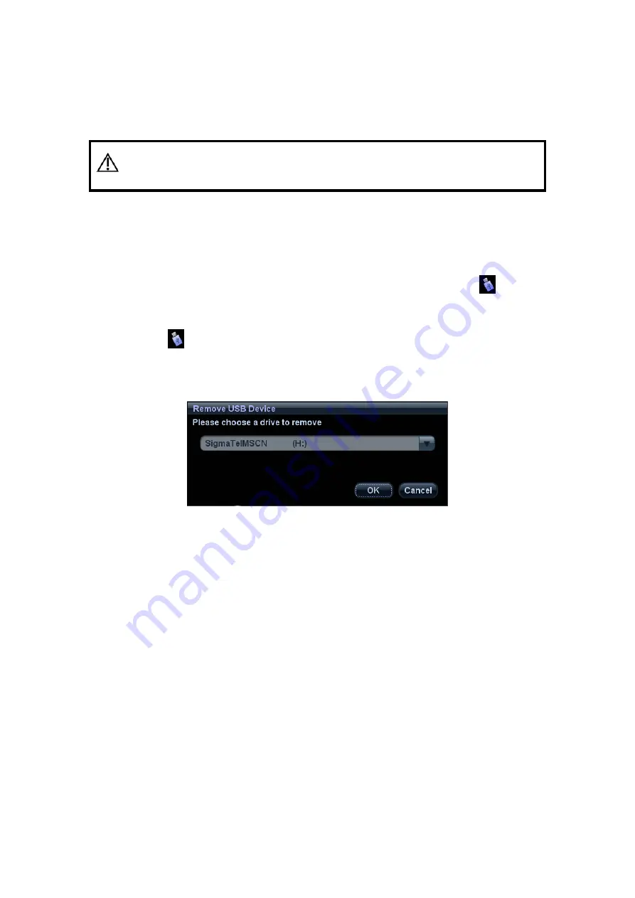
To remove the USB memory device:
(1) Click to open the “Remove USB Device” dialogue box.
(2) Select the memory device to be removed.
(3) Click [OK] and you can hear a sound. There will be sound feedback when remove
the USB memory device.
3.7.2 Connecting a Footswitch
Footswitch of different ports are supported by this system: one type is of USB port, and the
other type is of round port (two-pedal). Please connect the footswitch according to the
port.
Connection
Directly insert the USB port of the footswitch to the system applicable USB ports.
Summary of Contents for DC-T6
Page 1: ...DC T6 Diagnostic Ultrasound System Operator s Manual Basic Volume...
Page 2: ......
Page 10: ......
Page 16: ......
Page 28: ......
Page 37: ...System Overview 2 9 2 6 Introduction of Each Unit...
Page 178: ......
Page 182: ......
Page 236: ......
Page 240: ...13 4 Probes and Biopsy No Probe Model Type Illustration 19 CW2s Pencil probe...
Page 300: ......
Page 314: ......
Page 320: ......
Page 326: ......
Page 330: ...C 4 Barcode Reader...
Page 337: ...Barcode Reader C 11...
Page 342: ......
Page 347: ...P N 046 001523 01 V1 0...


