


Enhanced Serial Communication Interface (eSCI)
26-14
Freescale Semiconductor
PXR40 Microcontroller Reference Manual, Rev. 1
26.3.2.6
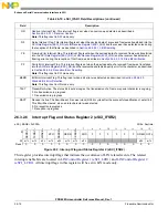
Interrupt Flag and Status Register 2 (eSCI_IFSR2)
This register provides interrupt flags that indicate the occurrence of LIN related events. The related
interrupt enable bits are located in
LIN Control Register 1 (eSCI_LCR1)
. All interrupt flags in this register will be set in LIN mode only.
OR
Overrun Interrupt Flag. This interrupt flag is set when an overrun was detected as described in
Section 26.4.5.3.11, Receiver Overrun
.
Note: This flag is set in SCI mode only.
NF
Noise Interrupt Flag. This interrupt flag is set when the payload data of a received frame was transferred into the
LIN Receive Register (eSCI_LRR)
and the receiver has detected noise during
the reception of that frame, as described in
Section 26.4.5.3.13, Bit Sampling
FE
Framing Error Interrupt Flag. This interrupt flag is set when the payload data of a received frame was transferred
into the
LIN Receive Register (eSCI_LRR)
and the receiver has detected a
framing error during the reception of that frame, as described in
Section 26.4.5.3.18, Stop Bit Verification
PF
Parity Error Interrupt Flag. This interrupt flag is set when the payload data of a received frame was transferred
into the
and the receiver has detected a parity error for the character, as described
Section 26.4.5.4, Reception Error Reporting
Note: This flag is set in SCI mode only.
BERR
Bit Error Interrupt Flag. This flag is set when a bit error was detected as described in
Note: This flag is set in LIN mode only.
TACT
Transmitter Active. The status bit is set as long as the transmission of a frame or special character is ongoing.
0 No transmission in progress.
1 Transmission in progress.
RACT
Receiver Active. The bit will be set 3 receiver clock (RCLK) cycles after the successful qualification of a start bit.
This bit will be cleared, when an idle character was detected.
0 No reception in progress.
1 Reception in progress.
eSC 0x000A
Write: Anytime
0
1
2
3
4
5
6
7
8
9
10
11
12
13
14
15
R
RXRD
Y
TXRD
Y
L
W
AKE
STO
PBERR
CERR
CKERR
FRC
0
0
0
0
0
0
UREQ OVFL
W w1c
w1c
w1c
w1c
w1c
w1c
w1c
w1c
w1c
w1c
Reset
0
0
0
0
0
0
0
0
0
0
0
0
0
0
0
0
Figure 26-7. Interrupt Flag and Status Register 2 (eSCI_IFSR2)
Table 26-10. eSCI_IFSR1 Field Descriptions (continued)
Field
Description
Summary of Contents for PXR4030
Page 1: ...PXR40 Microcontroller Reference Manual Devices Supported PXR4030 PXR4040 PXR40RM Rev 1 06 2011...
Page 30: ...PXR40 Microcontroller Reference Manual Rev 1 Freescale Semiconductor xxx...
Page 40: ...PXR40 Microcontroller Reference Manual Rev 1 xl Freescale Semiconductor...
Page 66: ...Memory Map PXR40 Microcontroller Reference Manual Rev 1 2 4 Freescale Semiconductor...
Page 120: ...Signal Descriptions 3 54 Freescale Semiconductor PXR40 Microcontroller Reference Manual Rev 1...
Page 860: ...FlexCAN Module 24 50 Freescale Semiconductor PXR40 Microcontroller Reference Manual Rev 1...
Page 1167: ...Decimation Filter Freescale Semiconductor 28 53 PXR40 Microcontroller Reference Manual Rev 1...
Page 1168: ...Decimation Filter 28 54 Freescale Semiconductor PXR40 Microcontroller Reference Manual Rev 1...


