


Frequency Modulated Phase-Locked Loop (FMPLL)
6-14
Freescale Semiconductor
PXR40 Microcontroller Reference Manual, Rev. 1
6.4
Functional Description
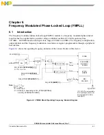
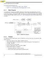
The FMPLL module contains the frequency modulated phase lock loop (FMPLL), enhanced frequency
divider (ERFD), enhanced synthesizer control registers (ESYNCR1 and ESYNCR2), synthesizer status
register (SYNSR), synthesizer FM control register (SYNFMCR) and clock/PLL control logic. The block
also contains a reference frequency pre-divider controlled by the EPREDIV bits in the ESYNCR1. This
enables the user to use a high frequency crystal or external clock generator and obtain finer frequency
synthesis resolution than would be available if the raw input clock were used directly by the analog loop.
For the remainder of this chapter, the term “reference frequency” and the symbol F
ref
indicate the output
of the pre-divider circuit. This is the clock on which frequency multiplication is performed.
6.4.1
General
The system clock source is determined during reset as shown in
. The value of the PLLCFG[0:1]
pins are latched during reset. If PLLCFG[0:1] are changed during a reset other than power-on reset, the
internal clocks may glitch as the clock source is changed between PLL Off mode and PLL clock mode or
from one PLL clock mode to another. Whenever PLLCFG[0:1] are changed in reset to a value other than
what it was before the reset, an immediate loss of lock condition is declared. This only applies if the PLL
was running in a locked state prior to the assertion of reset and change of PLLCFG[0:1].
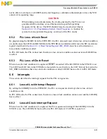
shows the PLL clock to input clock frequency relationships for the available clock modes.
6.4.2
PLL Off Mode
When PLL Off mode is selected, the PLL is turned off. The user must supply an external clock on the
EXTAL pin and select that clock source before entering PLL Off mode. The selected clock is directly used
to produce the various system clocks. Refer to
PXR40 Microcontroller Data Sheet
for external clock input
requirements. In PLL Off mode, the analog portion of the PLL is disabled, the frequency modulation
capability is not available, and no clocks are generated at the PLL output. The pre-divider is bypassed and
has no effect on the system clock frequency in PLL Off mode.
6.4.3
Normal Mode
When normal PLL mode is selected, the PLL is fully programmable. The PLL can synthesize frequencies
ranging from 48x to 148x the reference frequency of the output of the predivider, with or without
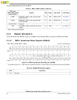
Table 6-10. Clock-Out vs. Clock-In Relationships
Clock Mode
Frequency Equation
PLL Off Mode
F
PLL
= F
extal
Normal PLL Mode
1
1
Equation to be used when programming enhanced control registers
(ESYNCR1 and ESYNCR2). See EPREDIV, EMFD, and ERFD bitfield
descriptions for valid ranges for these fields.
F
PLL
F
extal
EMFD
16
+
EPREDIV
1
+
ERFD
1
+
---------------------------------------------------------------------------
=
Summary of Contents for PXR4030
Page 1: ...PXR40 Microcontroller Reference Manual Devices Supported PXR4030 PXR4040 PXR40RM Rev 1 06 2011...
Page 30: ...PXR40 Microcontroller Reference Manual Rev 1 Freescale Semiconductor xxx...
Page 40: ...PXR40 Microcontroller Reference Manual Rev 1 xl Freescale Semiconductor...
Page 66: ...Memory Map PXR40 Microcontroller Reference Manual Rev 1 2 4 Freescale Semiconductor...
Page 120: ...Signal Descriptions 3 54 Freescale Semiconductor PXR40 Microcontroller Reference Manual Rev 1...
Page 860: ...FlexCAN Module 24 50 Freescale Semiconductor PXR40 Microcontroller Reference Manual Rev 1...
Page 1167: ...Decimation Filter Freescale Semiconductor 28 53 PXR40 Microcontroller Reference Manual Rev 1...
Page 1168: ...Decimation Filter 28 54 Freescale Semiconductor PXR40 Microcontroller Reference Manual Rev 1...


