


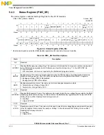


Power Management Controller (PMC)
5-14
Freescale Semiconductor
PXR40 Microcontroller Reference Manual, Rev. 1
5.5
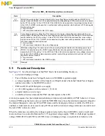
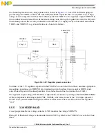
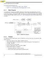
Functional Description
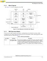
for a block diagram of the PMC block. Its main building blocks are
•
a precision bandgap voltage
•
Power On Reset and Low Voltage Detector on VDDREG regulator supply
•
a voltage regulator controller with a linear Low Drop Out and a Switched Mode Power Supply
options selectable via the REGSEL control
•
POR and LVD on VDD digital core supply
•
a 3.3V LDO regulator, with its relative 3.3V LVD
•
a digital interface to core logic
•
an interface between measurable PMC internal signals to the ADC
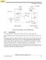
A start-up sequence has been implemented aiming at improved predictability of PMC behavior. A loose
tolerance POR keeps the device in reset until the VDDREG rises above the minimum required voltage for
the internal bandgap to come up. When POR clears and the band gap reference is stable, the LVDs are
enabled. A dedicated circuit is used to keep LVDs set until current and voltage references are stable and
the real LVDs’ values are valid.
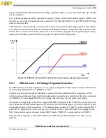
When the references are stable, the voltage regulator (selected by the pin REGSEL) enters in soft start
mode and rises in a controlled fashion the 1.2V regulated voltage supply VDD. As both target regulated
voltage VDD12OUT and LVD level LVD12 rely on bandgap voltage, an equivalent variation is to be
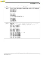
27
LVF33
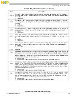
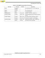
VDDSYN low-voltage flag. This read-only bit is the low-voltage flag associated with the VDDSYN 3.3 V
supply. It is asserted when the 3.3 V supply falls below the corresponding LVD threshold, and can be cleared
by the CPU by writing 1 to the LVFC33 bit. If the LVIE33 bit is also asserted, a low-voltage interrupt is sent
to the CPU. If LVRE33 is also asserted, a system reset will be generated, which will clear LVF33 and negate
the interrupt request.
0 No occurrence.
1 LVD occurrence detected on the 3.3V supply.
28
LVFC
Core-voltage-supply low-voltage flag. This read-only bit is the low-voltage flag associated with the core
voltage supply. It is asserted when the core voltage supply falls below the corresponding LVD threshold, and
can be cleared by the CPU by writing 1 to the LVFCC bit. If the LVIEC bit is also asserted, a low-voltage
interrupt is sent to the CPU. If LVREC is also asserted, a system reset will be generated, which will clear
LVFC and negate the interrupt request.
0 No occurrence.
1 LVD occurrence detected on the core voltage supply.
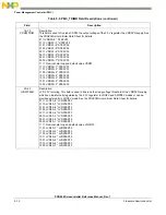
29
LVFA
VDDA low-voltage flag. This read-only bit is the low-voltage flag associated with the analog power input
VDDA1. It is asserted when the VDDA1 supply falls below its corresponding LVD threshold, and can be
cleared by the CPU by writing 1 to the LVFCA bit. If the LVIEA bit is also asserted, a low-voltage interrupt is
sent to the CPU. If LVREA is also asserted, a system reset will be generated, which will clear LVFA and
negate the interrupt request.
0 No occurrence.
1 LVD occurrence detected on the VDDA1 supply.
30–31
Reserved
Table 5-6. PMC_SR Field Descriptions (continued)
Field
Description
Summary of Contents for PXR4030
Page 1: ...PXR40 Microcontroller Reference Manual Devices Supported PXR4030 PXR4040 PXR40RM Rev 1 06 2011...
Page 30: ...PXR40 Microcontroller Reference Manual Rev 1 Freescale Semiconductor xxx...
Page 40: ...PXR40 Microcontroller Reference Manual Rev 1 xl Freescale Semiconductor...
Page 66: ...Memory Map PXR40 Microcontroller Reference Manual Rev 1 2 4 Freescale Semiconductor...
Page 120: ...Signal Descriptions 3 54 Freescale Semiconductor PXR40 Microcontroller Reference Manual Rev 1...
Page 860: ...FlexCAN Module 24 50 Freescale Semiconductor PXR40 Microcontroller Reference Manual Rev 1...
Page 1167: ...Decimation Filter Freescale Semiconductor 28 53 PXR40 Microcontroller Reference Manual Rev 1...
Page 1168: ...Decimation Filter 28 54 Freescale Semiconductor PXR40 Microcontroller Reference Manual Rev 1...


