


Core (e200z7) Overview
PXR40 Microcontroller Reference Manual, Rev. 1
Freescale Semiconductor
13-9
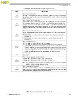
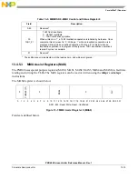
16
ICEI
Instruction Cache Error Injection Enable
0 Cache Error Injection is disabled
1 When ICEDT=00, parity errors will be purposefully injected into every byte
subsequently written into the cache. The parity bit of each 8-bit data element written
will be inverted on cache linefills. When ICEDT=01, a double-bit error will be injected
into each doubleword written into the cache by inverting the two uppermost parity
check bits (p_chk[0:1]).
ICEI will cause injection of errors regardless of the setting of ICECE, although reporting
of errors will be masked when ICECE=0.
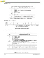
17
Reserved
18–19
ICEDT
Instruction Cache Error Detection Type
00 Parity Error Detection is selected for both the tag and data arrays Reserved
(defaults to ICEDT=01(EDC) actions)
01 EDC Error Detection is selected
1x Reserved
20
Reserved
21
ICUL
Instruction Cache Unable to Lock
Indicates a lock set instruction was not effective in locking a cache line. This bit is set
by hardware on an “unable to lock” condition (other than lock overflows), and will remain
set until cleared by software writing 0 to this bit location.
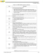
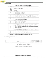
22
ICLO
Instruction Cache Lock Overflow
Indicates a lock overflow (overlocking) condition occurred. This bit is set by hardware
on an “overlocking” condition, and will remain set until cleared by software writing 0 to
this bit location.
23
ICLFC
Instruction Cache Lock Bits Flash Clear
When written to a ‘1’, a cache lock bits flash clear operation is initiated by hardware.
Once complete, this bit is reset to ‘0’. Writing a ‘1’ while a flash clear operation is in
progress will result in an undefined operation. Writing a ‘0’ to this bit while a flash clear
operation is in progress will be ignored. Cache Lock Bits Flash Clear operations require
approximately 134 cycles to complete. Clearing occurs regardless of the enable (ICE)
value.
24
ICLOA
Instruction Cache Lock Overflow Allocate
Set by software to allow a lock request to replace a locked line when a lock overflow
situation exists.
0 Indicates a lock overflow condition will not replace an existing locked line with the
requested line
1 Indicates a lock overflow condition will replace an existing locked line with the
requested line
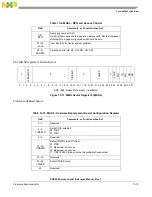
25–26
ICEA
Instruction Cache Error Action
00 Error Detection causes Machine Check exception.
01 Error Detection causes Correction/Auto-invalidation. No machine check is
generated unless a locked line is invalidated. Correction is performed for single-bit
tag and lock errors, and lines with multi-bit tag or lock errors are invalidated. In parity
mode, tag or lock errors will result in invalidation of lines. Correction is performed
for single or multi-bit data errors by reloading of the line.
1x Reserved
27–28
Reserved
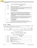
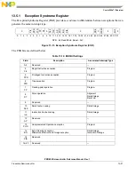
Table 13-2. L1CSR1 Field Descriptions (continued)
Field
Description
Summary of Contents for PXR4030
Page 1: ...PXR40 Microcontroller Reference Manual Devices Supported PXR4030 PXR4040 PXR40RM Rev 1 06 2011...
Page 30: ...PXR40 Microcontroller Reference Manual Rev 1 Freescale Semiconductor xxx...
Page 40: ...PXR40 Microcontroller Reference Manual Rev 1 xl Freescale Semiconductor...
Page 66: ...Memory Map PXR40 Microcontroller Reference Manual Rev 1 2 4 Freescale Semiconductor...
Page 120: ...Signal Descriptions 3 54 Freescale Semiconductor PXR40 Microcontroller Reference Manual Rev 1...
Page 860: ...FlexCAN Module 24 50 Freescale Semiconductor PXR40 Microcontroller Reference Manual Rev 1...
Page 1167: ...Decimation Filter Freescale Semiconductor 28 53 PXR40 Microcontroller Reference Manual Rev 1...
Page 1168: ...Decimation Filter 28 54 Freescale Semiconductor PXR40 Microcontroller Reference Manual Rev 1...


