


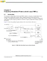
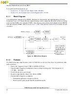
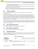


Power Management Controller (PMC)
5-18
Freescale Semiconductor
PXR40 Microcontroller Reference Manual, Rev. 1
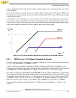
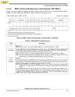
The assertion and negation voltages are adjustable via software by writing to the LVD33TRIM field of the
PMC_TRIMR register, which selects one of the 16 voltages available through the appropriate tapped
output. The reset and default value of the 4-bit register is “1111”, corresponding to the nominal LVD33
voltage.
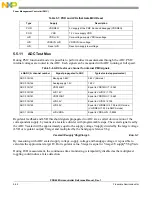
LVD scaled voltage can be measured via ADC by selecting the respective channel reported in
.
During this measurement, the output of the LVD is temporarily forced to low level so that false events,
which may be caused by ADC reading, are discarded.
5.5.6
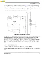
1.2V Voltage Regulator Controller
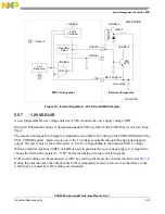
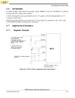
A double Voltage Regulator Controller (VRC) is implemented in this power management system. It is
composed of a linear LDO VRC, and an SMPS VRC. A soft startup block slews the output voltage of the
regulator output smoothly in order to avoid ringing or over voltage condition and steep voltage and current
slopes. A block diagram of the regulator is shown in
The LDO Voltage Regulator Controller is designed to drive an external bipolar transistor and relative
decoupling capacitance at bipolar emitter. A smaller compensation capacitor might be required on
REGCTL, depending on the external bipolar selected.
The switched controller is a full analog asynchronous regulator, with ramp compensation and equalized
error integration. It is used to drive an external high side n-MOS driver / Schottky diode.The regulator
output voltage is adjustable using software, to permit the device to center the supply for maximum
transient margin.
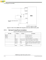
The feedback of the regulation loop comes from the VDD core voltage through a trimmable resistive
divider. By adjusting the trimming control 4-bit word VDDCTRIM it is possible to adjust the regulator
target DC output voltage VDD12OUT during device operation, with 16 voltage steps of size STEPV12,
around the typical regulator target voltage. The reset value, start up and default condition of the 4-bit
register is “1111”.
Tolerance of the 1.2V regulators, reported in the
PXR40 Microcontroller Data Sheet
, assumes appropriate
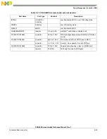
external active and passive devices as reported in bill of materials
Section 5.7.2, Hardware Design
, maximum current load less than or equal to
Idd12
, and a correct board layout with
reduced parasitics. It excludes line and load variation above 10 kHz.
The 1.2V supply is internally connected to an ADC channel so that the actual voltage may be read by the
microcontroller.
The suitable external driver has an automotive range temperature profile and
•
In case of NPN device a minimum beta of 50, maximum current rating >1.5A;
•
In case of high side driver maximum threshold voltage of 1.5V, gate capacitance less than 5nF,
maximum current rating >2A.
Summary of Contents for PXR4030
Page 1: ...PXR40 Microcontroller Reference Manual Devices Supported PXR4030 PXR4040 PXR40RM Rev 1 06 2011...
Page 30: ...PXR40 Microcontroller Reference Manual Rev 1 Freescale Semiconductor xxx...
Page 40: ...PXR40 Microcontroller Reference Manual Rev 1 xl Freescale Semiconductor...
Page 66: ...Memory Map PXR40 Microcontroller Reference Manual Rev 1 2 4 Freescale Semiconductor...
Page 120: ...Signal Descriptions 3 54 Freescale Semiconductor PXR40 Microcontroller Reference Manual Rev 1...
Page 860: ...FlexCAN Module 24 50 Freescale Semiconductor PXR40 Microcontroller Reference Manual Rev 1...
Page 1167: ...Decimation Filter Freescale Semiconductor 28 53 PXR40 Microcontroller Reference Manual Rev 1...
Page 1168: ...Decimation Filter 28 54 Freescale Semiconductor PXR40 Microcontroller Reference Manual Rev 1...


