


Deserial Serial Peripheral Interface (DSPI)
25-26
Freescale Semiconductor
PXR40 Microcontroller Reference Manual, Rev. 1
Address: DSP 0xBC
Access: R/W
0
1
2
3
4
5
6
7
8
9
10
11
12
13
14
15
R
MTOE
0
MTOCNT
0
0
0
TSBC TXSS TPOL TRRE
CID
W
Reset
0
0
0
0
0
0
0
0
0
0
0
0
0
0
0
0
16
17
18
19
20
21
22
23
24
25
26
27
28
29
30
31
R
DCONT
DSICTAS
0
0
0
0
0
0
DPCS5
DPCS4
DPCS3
DPCS2
DPCS1
DPCS0
W
Reset
0
0
0
0
0
0
0
0
0
0
0
0
0
0
0
0
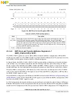
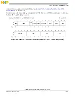
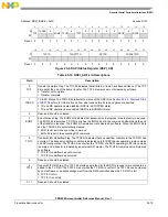
Figure 25-12. DSPI DSI Configuration Register (DSPI_DSICR)
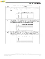
Table 25-20. DSPI_DSICR Field Descriptions
Field
Description
0
MTOE
Multiple Transfer Operation Enable. The MTOE bit enables multiple DSPIs to be connected in a
parallel or serial configuration. See
Section 25.4.4.6, Multiple Transfer Operation (MTO)
, for more
information.
0 Multiple Transfer Operation disabled
1 Multiple Transfer Operation enabled
The MTOE feature is not supported in TSB configuration and should be disabled in this mode.
1
Reserved, should be cleared.
2–7
MTOCNT
Multiple Transfer Operation Count. The MTOCNT field selects number of bits to be shifted out during
a transfer in Multiple Transfer Operation. The field sets the number of SCK cycles that the bus Master
will generate to complete the transfer. The number of SCK cycles used will be one more than the value
in the MTOCNT field. The number of SCK cycles defined by MTOCNT must be equal to or greater
than the frame size. When TSBC is set, MTOCNT is not used, and its value is ignored.
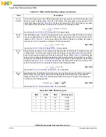
8–10
Reserved, should be cleared.
11
TSBC
Timed Serial Bus Configuration. The TSBC bit enables the Timed Serial Bus Configuration. This
configuration allows 32-bit data to be used. It also allows t
DT
to be programmable. See
, for detailed information.
0 Timed Serial Bus Configuration disabled
1 Timed Serial Bus Configuration enabled
If this bit is 0 the DSPI_DSICR1 register should not be used.
12
TXSS
Transmit Data Source Select. The TXSS bit selects the source of data to be serialized. The source
can be either data from host Software written to the DSPI DSI Alternate Serialization Data Register
(DSPI_ASDR), or Parallel Input pin states latched into the DSPI DSI Serialization Data Register
(DSPI_SDR).
0 Source of serialized data is the DSPI_SDR
1 Source of serialized data is the DSPI_ASDR
13
TPOL
Trigger Polarity. The TPOL bit selects the active edge of the hardware trigger input signal (HT). The
bit selects which edge will initiate a transfer in the DSI configuration. See
, for more information. When TSBC bit is set, bits TPOL bit is used for both
DSICR and DSICR1 registers.
0 Falling edge will initiate a transfer
1 Rising edge will initiate a transfer
Summary of Contents for PXR4030
Page 1: ...PXR40 Microcontroller Reference Manual Devices Supported PXR4030 PXR4040 PXR40RM Rev 1 06 2011...
Page 30: ...PXR40 Microcontroller Reference Manual Rev 1 Freescale Semiconductor xxx...
Page 40: ...PXR40 Microcontroller Reference Manual Rev 1 xl Freescale Semiconductor...
Page 66: ...Memory Map PXR40 Microcontroller Reference Manual Rev 1 2 4 Freescale Semiconductor...
Page 120: ...Signal Descriptions 3 54 Freescale Semiconductor PXR40 Microcontroller Reference Manual Rev 1...
Page 860: ...FlexCAN Module 24 50 Freescale Semiconductor PXR40 Microcontroller Reference Manual Rev 1...
Page 1167: ...Decimation Filter Freescale Semiconductor 28 53 PXR40 Microcontroller Reference Manual Rev 1...
Page 1168: ...Decimation Filter 28 54 Freescale Semiconductor PXR40 Microcontroller Reference Manual Rev 1...


