


Enhanced Time Processing Unit (eTPU2)
Freescale Semiconductor
29-89
PXR40 Microcontroller Reference Manual, Rev. 1
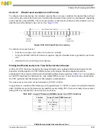
is entered after the pin has just gone high. Thread 3, the thread that is entered after the pin has just
gone low, requires only 2 CPU clocks. Therefore, in the first-pass example, the high time was
correctly derived, but the low time is actually shorter than was estimated.
29.4.2.5.2
Second-Pass Analysis Example
This example requires three 50% PWM waveforms: one 5 kHz (200 ms/period) and two 50 kHz (20
ms/period), each running DC motors. (Remember that the PWM function requests service from the eTPU
after each high time and after each low time, so the eTPU must handle a request every 100 ms for the 5
kHz PWM and every 10 ms for the 50 MHz PWM.)
NOTE
This example uses square waves for simplicity. Notice that to use a PWM
waveform in the typical way, in which the pulse is modulated, the pulse
must not be modulated in a way that violates the worst-case latency
requirements.
This example also uses one DIO channel monitoring a signal level every millisecond and one PPWA
channel in mode 0 monitoring the speed of the 5-kHz DC motor. The PPWA must measure periods of 5
kHz (200 ms/period).
The CPU is interrupted by the channel running the PPWA function after measuring 200 periods (every 40
ms). The interrupt service routine performs an averaging of the period accumulation and checks it against
a known parameter. The interrupt service time is so short and infrequent that it is a tiny fraction of total
system time. The interrupt service routine contains no polling of the SDM. Therefore a realistic RCR = 0%.
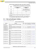
First-Try System Configuration
Try a system configuration that seems likely to work. If it does not, change priority levels or channel
numbers.
The 5 kHz and 50 kHz PWMs are the most time-critical functions. Those are assigned high priority. PPWA
is assigned middle priority. The DIO is low performance and is assigned low priority. Refer to
.
With this system configuration, worst-case service time for each active channel is determined as follows:
a.
Longest thread of PWM is 24 CPU clocks with four RAM accesses.
24 + ((4 RAM a1) * 0 * 2 CPU clock waits) = 24 CPU clocks
Table 29-26. First-Try System Configuration
Channel
Priority
Function
1
,
2
1
0% RAM collision rate
2
CPU clock rate = 40 MHz, or 60 ns per clock period
0
High
PWM at 50 kHz (needs a 4-
s WCL)
1
High
PWM at 50 kHz (needs a 4-
s WCL)
2
High
PWM at 5 kHz (needs a 40-
s WCL)
8
Middle
PPWA at 5 kHz (needs a 80-
s WCL)
15
Low
DIO as input at rate of 1 ms
Summary of Contents for PXR4030
Page 1: ...PXR40 Microcontroller Reference Manual Devices Supported PXR4030 PXR4040 PXR40RM Rev 1 06 2011...
Page 30: ...PXR40 Microcontroller Reference Manual Rev 1 Freescale Semiconductor xxx...
Page 40: ...PXR40 Microcontroller Reference Manual Rev 1 xl Freescale Semiconductor...
Page 66: ...Memory Map PXR40 Microcontroller Reference Manual Rev 1 2 4 Freescale Semiconductor...
Page 120: ...Signal Descriptions 3 54 Freescale Semiconductor PXR40 Microcontroller Reference Manual Rev 1...
Page 860: ...FlexCAN Module 24 50 Freescale Semiconductor PXR40 Microcontroller Reference Manual Rev 1...
Page 1167: ...Decimation Filter Freescale Semiconductor 28 53 PXR40 Microcontroller Reference Manual Rev 1...
Page 1168: ...Decimation Filter 28 54 Freescale Semiconductor PXR40 Microcontroller Reference Manual Rev 1...


