
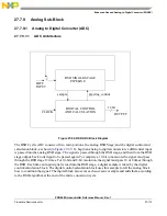


Enhanced Queued Analog-to-Digital Converter (EQADC)
27-118
Freescale Semiconductor
PXR40 Microcontroller Reference Manual, Rev. 1
a.
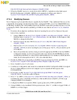
Write 0b0001 to the MODE0 field in EQADC_CFCR0 to program CFIFO0 for software
single-scan mode.
b.
Write “1” to SSE0 to assert SSS0 and trigger CFIFO0.
7. Since CFIFO0 is in single-scan software mode and it is also the highest priority CFIFO, the EQADC
starts to transfer configuration commands to the on-chip ADCs and to the external device.
8. When all of the configuration commands have been transferred, CF0 in
FIFO and Interrupt Status Registers (EQADC_FISR)
, will be set. The EQADC generates a End of
Queue interrupt. The initialization procedure is complete.
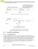
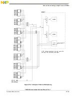
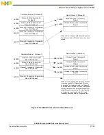
Figure 27-73. Example of a CQueue Configuring the On-Chip ADCs/External Device
The initialization procedure described above does not generate ADC clocks that are in phase because the
timing at which the ADC0/1_EN bits, in the
Section 27.6.3.1, ADC0/1 Control Registers (ADC0_CR and
, are set is different. Below follows an example on how to simultaneously set these bits so that
in-phase ADC clocks are generated. In this example, ADC0/1_CLK are configured to the same frequency.
1.
Push an ADC0_CR write configuration command in CFIFO0 that enables ADC0 (ADC0_EN=1)
and that sets the ADC0_CLK_PS to an appropriate value. For example, 0x80800801.
2.
Push an ADC1_CR write configuration command in CFIFO1 that enables ADC1 (ADC1_EN=1)
and that sets the ADC1_CLK_PS to an appropriate value. For example, 0x82800801.
3.
Configure CFIFO0 and CFIFO1 to single scan software trigger mode and simultaneously trigger
them by writing 0x04100410 to the EQADC_CFCR0 register - see
CFIFO Control Registers (EQADC_CFCR)
27.8.1.2
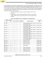
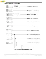
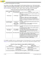
Configuring EQADC for Applications
This section provides an example based on the applications in
. The example describes how to
configure multiple CQueues to be used for those applications and provides a step-by-step procedure to
configure the EQADC and the associated CQueue structures. In the example, the “Fast hardware-triggered
CQueue”, described on the second row of
, will have its commands transferred to CBuffer1;
the conversion commands will be executed by ADC1. The generated results will be returned to RFIFO3
before being transferred to the RQueues in the RAM by the DMAC.
Configuration Command to CBuffer0 - Ex: Write ADC0_CR
CQueue in
0x0
0x1
0x2
0x3
system memory
Configuration Command to CBuffer2 - Ex: Write to external device configuration register
Configuration Command to CBuffer0 - Ex: Write ADC_TSCR
Configuration Command to CBuffer1 - Ex: Write ADC1_CR
Command
Address
Summary of Contents for PXR4030
Page 1: ...PXR40 Microcontroller Reference Manual Devices Supported PXR4030 PXR4040 PXR40RM Rev 1 06 2011...
Page 30: ...PXR40 Microcontroller Reference Manual Rev 1 Freescale Semiconductor xxx...
Page 40: ...PXR40 Microcontroller Reference Manual Rev 1 xl Freescale Semiconductor...
Page 66: ...Memory Map PXR40 Microcontroller Reference Manual Rev 1 2 4 Freescale Semiconductor...
Page 120: ...Signal Descriptions 3 54 Freescale Semiconductor PXR40 Microcontroller Reference Manual Rev 1...
Page 860: ...FlexCAN Module 24 50 Freescale Semiconductor PXR40 Microcontroller Reference Manual Rev 1...
Page 1167: ...Decimation Filter Freescale Semiconductor 28 53 PXR40 Microcontroller Reference Manual Rev 1...
Page 1168: ...Decimation Filter 28 54 Freescale Semiconductor PXR40 Microcontroller Reference Manual Rev 1...


