


Enhanced Queued Analog-to-Digital Converter (EQADC)
Freescale Semiconductor
27-97
PXR40 Microcontroller Reference Manual, Rev. 1
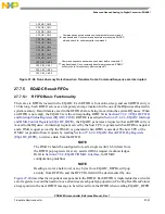
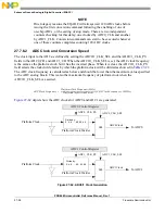
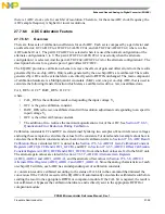
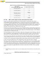
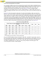
The ADC conversion speed (in K samples per second - Ksps) is calculated by the following formula. T
he
number of sampling cycles
is determined by the LST bits in the command message — see
Command Format for the Standard Configuration
— and it can take one of the following values: 2, 8, 64,
or 128 ADC clock cycles. The
number of AD conversion cycles
is 13 for differential conversions and 14
for single-ended conversions (12 bits resolution and unitary input gain). The maximum conversion speed
is achieved when the ADC Clock frequency is set to its maximum, the number of sampling cycles set to
its minimum (2 cycles), and the resolution is also set to the minimum (8 bits) with input unitary gain.
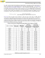
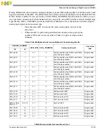
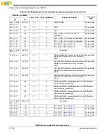
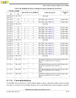
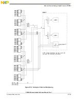
shows an example of how the ADC0/1_CLK_PS can be set when using a 120 MHz platform
clock and the corresponding conversion speeds for all possible ADC clock frequencies. The table also
shows that according to the platform clock frequency, certain clock divide factors are invalid (2, 4, 6, 8
clock divide factors in the example) since their use would result in a ADC clock frequency higher than the
maximum one supported by the ADC. In this example, the maximum ADC clock frequency is 15 MHz (12
bits resolution conversions with unitary input gain).
Table 27-40. ADC Clock Configuration Example (Platform Clock Frequency=120 MHz)
ADC0/1_CLK_PS[0:4]
Platform Clock
Divide Factor
ADC Clock
(Platform Clock
= 120 MHz)
Differential
Conversion Speed
with Default Sampling
Time (2 cycles)
Single-Ended
Conversion Speed
with Default Sampling
Time (2 cycles)
0b00000
2
N/A
N/A
N/A
0b00001
4
N/A
N/A
N/A
0b00010
6
N/A
N/A
N/A
0b00011
8
15.0 MHz
1.0 Msps
938 Ksps
0b00100
10
12.0 MHz
800 Ksps
750 Ksps
0b00101
12
10.0 MHz
667 Ksps
625 Ksps
0b00110
14
8.57 MHz
571 Ksps
536 Ksps
0b00111
16
7.5 MHz
500 Ksps
469 Ksps
0b01000
18
6.67 MHz
444 Ksps
417 Ksps
0b01001
20
6.0 MHz
400 Ksps
375 Ksps
0b01010
22
5.45 MHz
364 Ksps
341 Ksps
0b01011
24
5.0 MHz
333 Ksps
313 Ksps
0b01100
26
4.62 MHz
308 Ksps
288 Ksps
0b01101
28
4.29 MHz
286 Ksps
268 Ksps
0b01110
30
4.0 MHz
267 Ksps
250 Ksps
0b01111
32
3.75 MHz
250 Ksps
234 Ksps
0b10000
34
3.53 MHz
235 Ksps
221 Ksps
0b10001
36
3.33 MHz
222 Ksps
208 Ksps
0b10010
38
3.16 MHz
211 Ksps
198 Ksps
0b10011
40
3.0 MHz
200 Ksps
188 Ksps
0b10100
42
2.86 MHz
190 Ksps
179 Ksps
0b10101
44
2.73 MHz
182 Ksps
170 Ksps
ADCConversionSpeed
ADCClockFrequency MHz
NumberOfSamplingCycles
NumberOfADConversionCycles
+
------------------------------------------------------------------------------------------------------------------------------------------------------------------------
=
Summary of Contents for PXR4030
Page 1: ...PXR40 Microcontroller Reference Manual Devices Supported PXR4030 PXR4040 PXR40RM Rev 1 06 2011...
Page 30: ...PXR40 Microcontroller Reference Manual Rev 1 Freescale Semiconductor xxx...
Page 40: ...PXR40 Microcontroller Reference Manual Rev 1 xl Freescale Semiconductor...
Page 66: ...Memory Map PXR40 Microcontroller Reference Manual Rev 1 2 4 Freescale Semiconductor...
Page 120: ...Signal Descriptions 3 54 Freescale Semiconductor PXR40 Microcontroller Reference Manual Rev 1...
Page 860: ...FlexCAN Module 24 50 Freescale Semiconductor PXR40 Microcontroller Reference Manual Rev 1...
Page 1167: ...Decimation Filter Freescale Semiconductor 28 53 PXR40 Microcontroller Reference Manual Rev 1...
Page 1168: ...Decimation Filter 28 54 Freescale Semiconductor PXR40 Microcontroller Reference Manual Rev 1...


