


Enhanced Queued Analog-to-Digital Converter (EQADC)
Freescale Semiconductor
27-59
PXR40 Microcontroller Reference Manual, Rev. 1
Conversion Command Format for Alternate Configurations
describes the format for conversion commands when interfacing with the on-chip ADCs in
one of the 8 alternate configurations. An alternate configuration is selected when the least significant byte
(bits 24-31) of the conversion command is set to a value in the range 0x08-0x0F. Each value in this range
selects one of the 8 alternate configuration (0x08 selects Alternate Configuration 1, 0x0F selects Alternate
Configuration 8). In the alternate configurations, the conversion result can be routed to one of the RFIFOs
or to the parallel side interface to communicate with an on-chip companion module (decimation filter). A
bit field in the corresponding Alternate Configuration Control Register selects the Internal RFIFO or
Parallel Side Interface as the destination for the conversion result. Time stamp information can be
optionally requested.
NOTE
All fields, except FFMT and ALT_CONFIG_SEL, are identical to the ones
in the standard configuration format. Only the fields which are different
from the standard format will be described here.
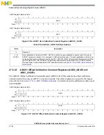
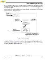
Figure 27-44. Conversion Command Format for Alternate Configurations
14
TSR
Time Stamp Request. TSR indicates the request for a time stamp. When TSR is asserted, the on-chip ADC
Control Logic returns a time stamp for the current conversion command after the conversion result is sent
to the RFIFOs. See
Section 27.7.6.3, Time Stamp Feature
, for details.
0 Return conversion result only.
1 Return conversion time stamp after the conversion result.
15
FMT
Conversion Data Format. FMT specifies to the EQADC how to format the 12-bit conversion data returned
by the ADCs into the 16-bit format which is sent to the RFIFOs. See
Section , ADC Result Format for
, for details.
0 Right justified unsigned.
1 Right justified signed.
16–23
CHANNEL_
NUMBER
Channel Number Field. The CHANNEL_NUMBER field selects the analog input channel. The software
programs this field with the channel number corresponding to the analog input pin to be sampled and
converted. See
Section 27.7.7.1, Channel Assignment
, for details.
24–31
Reserved
0
1
2
3
4
5
6
7
8
9
10
11
12
13
14
15
EOQ PAUSE REP RESERVED
EB
(0b0)
BN
CAL
MESSAGE_TAG
LST
TSR FFMT
CFIFO Header
ADC Command
16
17
18
19
20
21
22
23
24
25
26
27
28
29
30
31
CHANNEL_NUMBER
ALT_CONFIG_SEL
ADC Command
Table 27-32. Field Descriptions (continued)
Field
Description
Summary of Contents for PXR4030
Page 1: ...PXR40 Microcontroller Reference Manual Devices Supported PXR4030 PXR4040 PXR40RM Rev 1 06 2011...
Page 30: ...PXR40 Microcontroller Reference Manual Rev 1 Freescale Semiconductor xxx...
Page 40: ...PXR40 Microcontroller Reference Manual Rev 1 xl Freescale Semiconductor...
Page 66: ...Memory Map PXR40 Microcontroller Reference Manual Rev 1 2 4 Freescale Semiconductor...
Page 120: ...Signal Descriptions 3 54 Freescale Semiconductor PXR40 Microcontroller Reference Manual Rev 1...
Page 860: ...FlexCAN Module 24 50 Freescale Semiconductor PXR40 Microcontroller Reference Manual Rev 1...
Page 1167: ...Decimation Filter Freescale Semiconductor 28 53 PXR40 Microcontroller Reference Manual Rev 1...
Page 1168: ...Decimation Filter 28 54 Freescale Semiconductor PXR40 Microcontroller Reference Manual Rev 1...


