Parameters ASDA-B2-F
7-44
September, 2015
7
Settings:
0: Manual Mode
1: Auto Mode (continuous adjustment)
2: Semi-auto Mode (non-continuous adjustment)
Description of manual mode setting:
When P2-32 is set to 0, parameters related to gain control, such as P2-00, P2-02, P2-04, P2-06,
P2-07, P2-25 and P2-26, all can be set by the user. When switching mode from auto or semi-auto
mode to manual mode, gain-related parameters will be updated automatically.
Description of auto mode setting:
Continue to estimate the system inertia. Automatically save the load inertia ratio to P1-37 every 30
minutes and refer to the stiffness and bandwidth setting of P2-31.
1. Set the system to manual mode 0 from auto mode 1 or semi-auto mode 2. The system will save
the estimated load inertia value to P1-37 automatically and set the corresponding parameters.
2. Set the system to auto mode 1 or semi-auto mode 2 from manual mode 0. Please set appropriate
load inertia value in P1-37.
3. Set the system to manual mode 0 from auto mode 1. P2-00, P2-04 and P2-06 will be modified to
the corresponding parameters in auto mode.
4. Set the system to manual mode 0 from semi-auto mode 2. P2-00, P2-04, P2-06, P2-25 and P2-26
will be modified to the corresponding parameters in auto mode.
Description of semi-auto mode setting:
1. When the system inertia is stable, the value of P2-33 will be 1 and the system stops estimating.
The load inertia ratio will be saved to P1-37 automatically. When switching from other modes to
semi-auto mode (from manual mode or auto mode), the system starts to estimate again.
2. When the system inertia is over the range, the value of P2-33 will be 0 and the system starts to
estimate and adjust again.
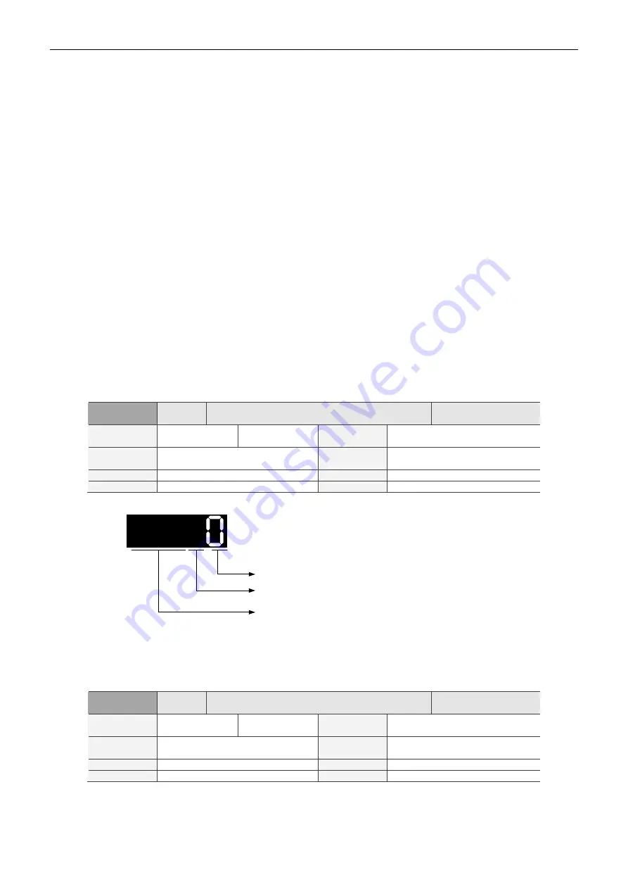
P2-33
▲
AUT3
Semi-auto Inertia Adjustment
Address: 0242H
0243H
Operational
Interface:
Panel / Software
Communication
Related
Section:
-
Default: 0
Control
Mode:
ALL
Unit: -
Range: 0 ~ 1
Format: DEC
Data Size: 16-bit
Settings:
Semi-auto setting
Reserved
Not in use
Semi-auto Setting:
1: It means the inertia estimation in semi-auto mode is completed. The inertia value can be
accessed via P1-37.
0: When the display is 0, it means the inertia adjustment is not completed yet and is still adjusting.
When the setting is 0, it means the inertia adjustment is not completed yet and is still adjusting.
P2-34
SDEV
Condition of Over Speed Warning
Address: 0244H
0245H
Operational
Interface:
Panel / Software
Communication
Related
Section:
-
Default: 5000
Control
Mode:
Sz
Unit: r/min
Range: 1 ~ 5000
Format: DEC
Data Size: 16-bit
Settings:
It is the setting for over speed warning in servo drive error display (P0-01).
Summary of Contents for ASD-B2-0121-F
Page 3: ...September 2015 This page is intentionally left blank...
Page 9: ...VI September 2015 This page is intentionally left blank...
Page 29: ...Installation ASDA B2 F 2 12 September 2015 2 This page is intentionally left blank...
Page 185: ...Parameters ASDA B2 F 7 68 September 2015 7 This page is intentionally left blank...
Page 199: ...Communications ASDA B2 F 8 14 September 2015 8...
Page 201: ...Communications ASDA B2 F 8 16 September 2015 8 This page is intentionally left blank...
Page 217: ...Troubleshooting ASDA B2 F 9 16 September 2015 9 This page is intentionally left blank...
Page 239: ...Absolute System ASDA B2 F 10 22 September 2015 10 This page is intentionally left blank...


