125 • Schlage • ENGAGE Managed Property User's Guide
Control Mobile Enabled Smart Lock
Installation and Commissioning
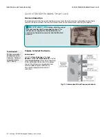
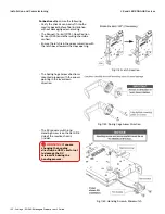
4. When plugging in the cable, be sure to
connect with the RED wire on the bottom. The
connecter is designed to fit in only one
orientation. DO NOT FORCE THIS
CONNECTION as connector damage is
possible.
5. When working with
INTERCONNECTED
units
(FE410), pay attention that the “Handing
Plate” and “Handing Screw” are installed
properly. Verify the lever catch is in the correct
orientation to allow proper lever installation
(Handing) as shown.
6. Once the Control Mobile Enabled Smart Lock
is properly installed:
• The thumb turn should physically move the
bolt in and out of the closed door and frame
smoothly without resistance.
• The outside thumb turn should spin freely
until a valid credential is presented.
• Interconnected lock smoothly retracts the
bolt whenever the inside lever is used with
no restrictions.
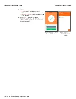
• Upon Power-up the Control Lock boots up,
flashes the
GREEN
LED and beeps 3 times.
This is the indication that it is ready for
Commissioning or Construction Mode
operation.
Fig. 11.4: Electrical Connection
Fig. 11.5: Handing Plate
Fig. 11.6: Handing Screw


