3.5.2 Customer connections
Introduction to customer connections
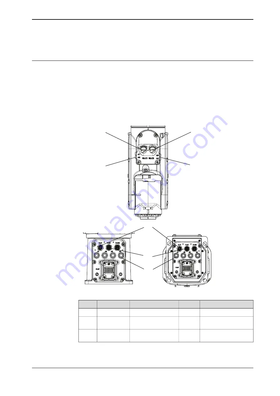
The cables for customer connection are integrated in the robot and the connectors
are placed on the wrist and one at the base. There is one connector R2.C1 at the
wrist. Corresponding connector R1.C1 is located at the base.
There is also connections for Ethernet, one connector R2.C2 at the wrist and the
corresponding connector R1.C2 located at the base.
Hose for compressed air is also integrated into the manipulator. There are 4 inlets
at the base (R1/8”) and 4 outlets (M5) on the wrist.
(A)
(B)
(C)
(A)
(B)
(C)
(C)
xx1900000131
Value
Number
Description
Connection
Position
30 V, 1.5 A
4 wires
i
Customer power/signal
(R1)R2.C1
A
30 V, 1 A or 1 Gbits/s
8 wires
ii
Customer power/signal
or Ethernet
(R1)R2.C2
B
Outer diameter of air hose:
4 mm
4
Max. 6 bar
Air
C
i
The connector has 12 pins. Only pins 5 to 8 are available for use. Pins 1 to 4 are used for LED
indicator, and pins 9 to 12 are not connected internally.
Continues on next page
Product manual - CRB 1100
91
3HAC078007-001 Revision: J
© Copyright 2021-2023 ABB. All rights reserved.
3 Installation and commissioning
3.5.2 Customer connections
Summary of Contents for CRB 1100
Page 1: ...ROBOTICS Product manual CRB 1100 ...
Page 162: ...This page is intentionally left blank ...
Page 184: ...This page is intentionally left blank ...
Page 652: ...This page is intentionally left blank ...
Page 698: ...This page is intentionally left blank ...
Page 712: ...This page is intentionally left blank ...
Page 714: ...This page is intentionally left blank ...
Page 719: ......


