Note
Action
Make sure the robot base is cor-
rectly fitted onto the pins.
Guide the robot gently, using the attachment
screws while lowering it into its mounting position.
7
Screws: M12x25 (robot installation
directly on foundation), 4 pcs,
quality 8.8
Fit the securing screws and washers in the attach-
ment holes of the base.
8
Washers: 4 pcs, 24 x 13 x 2.5
Tightening torque: 50 Nm±5 Nm
Tighten the bolts in a crosswise pattern to ensure
that the base is not distorted.
9
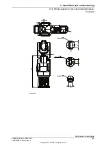
Hole configuration, base
This illustration shows the hole configuration used when securing the robot.
4x M12
11
11
10
4
135
135
6 H7
+
0.012
0
5.5
11.5
11.5
5.5
6 H7
+
0.012
0
4x R16
135
135
11
11
10
4
R16
11.5
5.5
6
A A
10
A-A
4x M12
11
11
10
4
135
135
6 H7
+
0.012
0
5.5
11.5
11.5
5.5
6 H7
+
0.012
0
4x R16
xx1800002448
Product manual - CRB 1100
57
3HAC078007-001 Revision: J
© Copyright 2021-2023 ABB. All rights reserved.
3 Installation and commissioning
3.3.2 Orienting and securing the robot
Continued
Summary of Contents for CRB 1100
Page 1: ...ROBOTICS Product manual CRB 1100 ...
Page 162: ...This page is intentionally left blank ...
Page 184: ...This page is intentionally left blank ...
Page 652: ...This page is intentionally left blank ...
Page 698: ...This page is intentionally left blank ...
Page 712: ...This page is intentionally left blank ...
Page 714: ...This page is intentionally left blank ...
Page 719: ......


